Hi - I have a basic knowledge of electrics but my boiler thermostat has flummoxed me 
My boiler is an ideal logic+ combi boiler that already has a center thermostat fitted - the receiver next to the boiler and a separate wireless thermostat controller.
I have dropped the controller and it is broken, so am looking to replace and thought about upgrading to the Tado thermostat.
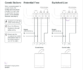
When I look at the center receiver wiring - I have a N, L and earth terminal which seem self explanatory - I assume this is my electrical connection to make it work.
I then have two other terminals connected - one marked A and one marked B. I think this is the boiler switch connection or certainly the connection to the boiler.
I also have a loop wire from the L terminal to the A terminal.
When I look at diagrams of the Tado receiver wiring, there are no terminals marked A or B. I have not bought the Tado system yet, as I want to make sure it is compatible to the wiring that I already have.
I have found one diagram online that looks like the A wire should be connected to the terminal CH NO and the B wire should be connected to the CH COM terminal. Is that correct or is it the reverse??
For the loop wire connected to the L terminal that currently goes to A - Where should that go to? The CH COM??
Any help appreciated and sorry if this is obvious!


