What do the regs say about sockets fed from portable UPS being RCD Protected?

Unless the earth is bonded to the neutral then the output will be floating and it is an IT supply.

Yes I get that the earth could be floating and not joined to Neutral, just like a petrol generator, but by saying

unit not to have a floating neutral

you made me think that neutral would be floating in regards against the Line. Appliances simply would not work then if there was no connection between Line and Neutral of course.

So it is likely the UPS could have a single fault to start with, the single fault is not a danger as which ever line it earths does not matter the fault will not cause a shock. What is the problem is a second fault could result in a shock, so we need to consider what the UPS is supplying.

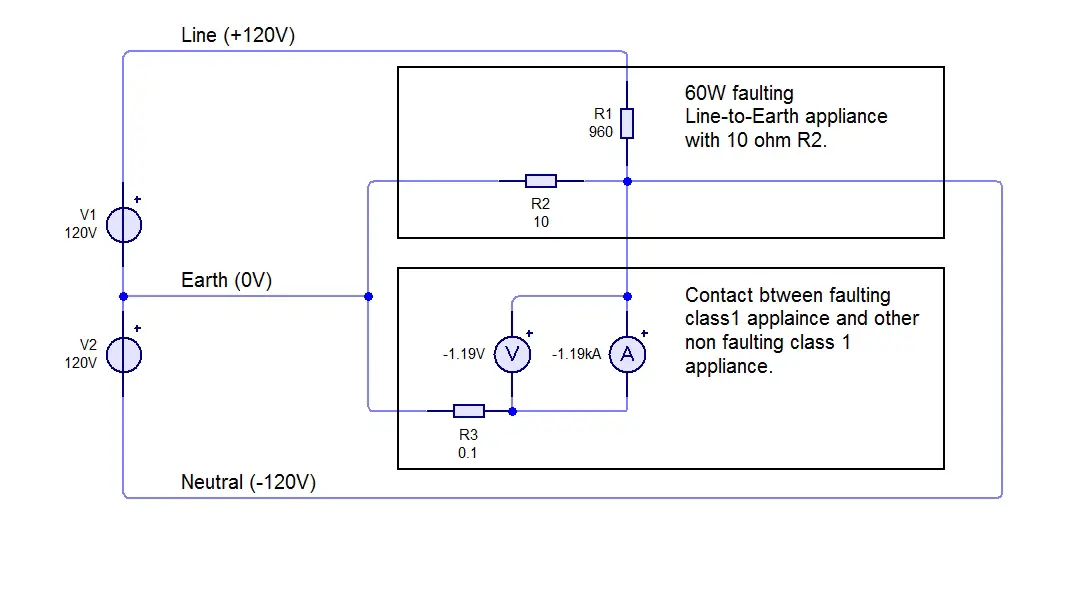
So it not a danger if one Class 1 appliance fed from the UPS has a L to E fault with a really high R2, and then you touch a another non-faulting class 1 device with a lower R2. Would you not get current flow and thus a shock between the faulting and non faulting device due to a difference in impedance?
 
Sponsored Links
whichever phase is drawing the most current pulls the voltage down on that phase and up on the other two.

Is the phase what gets pulled down due to voltage drop on that phase and the remaining two phases what get pulled up due to the two current return paths through each of the remaining two phases?

The voltage will drop on whichever phase has more current drawn, this will in essence pull the untethered star point voltage up (after the break) wrt the star point of the transformer. The other two phases connected to the untethered star point get more volts than usual. Then magic smoke escapes from the equipment!
I suppose as far as an UPS goes one would hope over voltage as well as under voltage would cause the UPS to turn to battery supply, and one would also hope there is some delay before it re-connects to the mains, so in the event of a lost neutral it would take over. However I would not bet on them taking over with over voltage. Likely only with under voltage will they take over, again with a delay it may still save the day.

It would not take much to design a device which auto turns off the supply should the voltage hit 260 volts, but I have only once in the UK been called to where the neutral has been lost, it is quite rare with the standard TN-C-S supply. Now in Algeria where the portacabins where supplied with three phase with one phase to each room in the portacabin we had loss of neutral quite a few times. And yes it did cause blue smoke to escape from low power appliances, but this problem is so rare with domestic supplies not to be worth fitting any device to auto disconnect should it happen.

But the question is about the lack of bonding between neutral and earth with small UPS powered from the 13A socket. If the output is left fully floating using a RCD is pointless. The question is does it really matter? Yes we can quote BS7671:2008 411.6 IT system and say what the regulations say, but is that really designed for small UPS?
(i) Insulation monitoring devices (IMDs)
(ii) Residual current monitoring devices (RCMs)
(iii) Insulation fault location systems
(iv) Overcurrent protective devices
Are really going OTT for such a small device.
411.6.3.1 Where an IT system is used for reasons of continuity of supply, an insulation monitoring device shall be provided to indicate the occurrence of a first fault from a live part to an exposed-conductive-part or to Earth. This device shall initiate an audible and or visual signal which shall continue as long as the fault persists. If there are both audible and visual signals it is permissible for the audible signal to be cancelled.
Seems to be aimed at UPS, the phrase "used for reasons of continuity of supply" does seem to show they are talking about an UPS. OK for a 5 kVA generator but does this really mean small 700W units?

So go on rip my comments apart, say what you think should be done and by whom, should the UPS have it built in or should the user install them separately? For all I know that 6 outlet using may be using 6 secondary windings on the step up transformer and each output could be isolated from the other, although I would not expect to find that. So what do you think is the correct approach to the problem?
 
So it not a danger if one Class 1 appliance fed from the UPS has a L to E fault with a really high R2, and then you touch a another non-faulting class 1 device with a lower R2. Would you not get current flow and thus a shock between the faulting and non faulting device due to a difference in impedance?
As long as the earths of every Class I item are bonded together you can't get neutral (which is really a line2) and line (should really call it line 1) both going to earth. Where the problem arises is where any earth bond is broken, the RCD will not help as unless there is current flow it will not work. The old ELCB-v would in this case actually work, and really that is what the RCM does. It assumes the voltage will be mid point with a line 1 and line 2 supply and often has resistors which will cause the earth to be mid point, if the earth voltage is say 50 volts from the central point it gives a warning, some actually have bar graphs to show the amount of leakage and once this is exceeded will auto disconnect the supply. But in essence they work on voltage not leakage current.

Although these could be built into the UPS they can't really be installed as a separate unit. It is the simple fact that the supply swaps from TN to IT when the UPS cuts in so the IT unit RCM would trip straight away on a TN supply.

So in real terms there is no way to add the protection device, either it is built into the UPS or you don't have it.

However I must thank you for pointing it out, I am uncertain of how it should be done, so welcome any comments.
 
Seems to be aimed at UPS, the phrase "used for reasons of continuity of supply" does seem to show they are talking about an UPS.
No. it's about IT systems, which are sometimes used to avoid a loss of supply from a single fault.
 
Sponsored Links
As long as the earths of every Class I item are bonded together you can't get neutral (which is really a line2) and line (should really call it line 1) both going to earth.

Appears your right, as the diagram below shows. Forgive the spelling errors in the diagram.

Realistic with 0.1Ω earth fault path through non faulting appliance:


Edit: Just getting overly confused now and really screwing things up big time.

:notworthy:o_O:censored: Laws of physics must be maintained and must not rely on what simulation programs say! I effectively was bypassing the voltmeter in my diagram thus getting 1.19V :notworthy::rolleyes:

1190(1.19Ka) X 0.1Ω = 119V - Ohm's Law

So now don't know if my diagram is realistic or not?
 
Last edited:
Major update: appears the earth is floating or nearly floating if that makes sense and is not centred tapped. Despite having 125V between N & E, the current draw between N & E is only around 1.5 mA.

Now question is what best thing for me to do other than quoted below or nothing, as said used to provide backup to network equipment in event of power outage until battery dies or power from grid is restored. Can't afford a insulation monitoring device.

RCDs can be used if there is no other device which disconnects on the first fault to ground, the RCD would disconnect on the second fault.
 
One are you sure there is not already protection built in

Earth Fault protection, No i am not sure. Could try doing a RCD test, although my second hand Seawood RCD tester is on the blink and is not tripping 30ma RCD's any more on the 1x and 5x setting.

and two with network equipment simply put them all in a cage and label the door authorised access only.

Network cabinet can and is normally locked, maybe I will change the socket and plug upstairs to a non standard type like a walsall or roundpin as some equipment has to be up there.

Would a round pin plug be suitable protection to ensure non-standard equipment what can be used outside can not be plugged in, Some how I doubt so!

Plus you also have the fact that the 4-way power strip under the table in the room upstairs feeding the Wireless AP and IP Cam power adaptors is still a standard socket type.
 
Last edited:
I had a real cheap 650W 12V inverter and even that shut down electronically on both L-E and N-E faults. Requiring the supply to be cycled to reset it.
 
Not entirely frivolous questions:

If one has some circuits in one's house, with sockets and/or buried cables, which are sometimes powered by a generator, is one's installation non-compliant when using a generator of the type where the RCD isn't going to work?

What if (I think JohnW2 has done this) you've got sockets which are only ever supplied from a genny, and could therefore never have RCD protection?
 
It is very basic thinking. The UPS generates AC power as a voltage between it G-Live and G-Neutral ( reason for G- will be clear later )

The current that leaves the generator on the G-Live ( or Line 1 ) must all return to the generator ( the UPS ) on the G-Neutral ( or Line 2 ). If the current on G-Live is not the same as the current on G-Neutral then some current is leaking away some where, that means there is a fault and possibly a risk of electric shock or fire.

So put an RCD sense coil around the G-Live and G-Neutral and if there is a difference the RCD trips and disconnects Live and Neutral.

If the only connections to the generator's output are G-Live and G-Neutral then there is no other path for current to return to the generator. That means that no matter what G-Live or G-Neutral come into contact with the current on G-Live at the RCD sensor coil will always be equal and opposite to the current on G-Neutral and therefore the RCD will never trip.

G-Live or G-Neutral could come into contact with ( normal ) Live at 230 volts and still the currents will be the same but the UPS output and the circuity in the load will 230 volt plus the UPS voltage which will mean either G-Live or G-Neutral could worst case have peak voltages of 644 volts ( (230+230)x√2 ).

ups-rcd.jpg


It gets difficult when stray capacity and other un-avoidable sneak circuits as shown in green have to be considered.

The fault to network Live (shown in red ) would via the stray capacitor in the UPS create a fault current along the G-Neutral and thus possibly trip the RCD but only if the stray capacity was large enough to pass the tripping current of the RCD ( 30 mA ) That trip would protect the UPS but not the load.

The fault in the load ( shown in purple ) would via two stray capacitors create a ground current and thus also a difference in the current in G-Live and G-Neutra and may trip the RCD depending on the size of the two stray capacitances in series and the ground impedance.


Creating a low impedance path from the UPS output to Ground would ensure the fault current in both cases would be higher than that via stray capacitance and thus more likely to be enough to trip the RCD.

The short between G-Neutral and network Live may seem improbable. Consider the situation where automatic change over switch is installed without ensured break before make durin th change over.
 
Last edited:
With a generator we normally have an earth rod and the generator is in some way bonded the line and neutral are both switched over and there is really no difference with the generator supply to the mains supply. There is also very little chance that a generator can be started quick enough for the power not to be lost for a few seconds. The problem with the generator in the main is refrigeration plants where they try to restart before the pressure has dropped causing them to trip out on overload. My instructions was always to wait 5 minutes before putting power back on purely to allow the pressure to drop first.

The whole point of the UPS is there is no power outage. No reboot or waiting for pressure to drop time, so idea of having contacts with minimum contact clearance is not really an option, it has to be a solid state switch.

There is a simple way around the problem, don't switch. A power supply can supply a battery and the battery supply an inverter so the devices are always supplied from the inverter. There is no reason which multi sources can't charge the battery so on a power failure the generator starts and that then supplies the battery so the battery has only got to last around a minute.

I had this system on a narrow boat, not because of power cuts, but because we only had a 4 amp shore supply and we wanted a 13 amp supply to run a washing machine and the batteries took up the slack.

The theroy is that solid state switches fail less often than an inverter.

We had an UPS in the Falklands due to the generators throwing fan belts and failing, by time the UPS was up and running we had cured the fan belt problem and the generators rarely failed. However the UPS failed more then the generators ever did and it was a complete waste of money.

To have emergency lighting makes sense, but if the supply to a computer fails the worry is it will corrupt the hard drive, having to reboot the computer is a minor problem everyone should save their work at least every half hour and if they don't they need their knuckles rapping.

What I have never quite understood is the server runs on DC, why do you need to protect a server with an AC supply? It should be easy to have twin power supplies each one from a separate source with a simple diode why we protect the 230 VAC supply I really don't know. Go into a telephone exchange and everything runs from 50 VDC and there are batteries everywhere.

But back to problem it is down to risk assessment. We all have to make a risk assessment every day of out lives, be it is it safe to cross the road to a complex task. My boss told me off for not having a spare length of overhead track in stock, he said the loss of production would cost £X per day and it would take two days to get a length of track which cost £X/8 so it was not worth the risk I should have one in stock.

The problem is the boss needs to tell you the cost. If he withholds the cost of a power cut you can't calculate the risk.
 
There is a simple way around the problem, don't switch. A power supply can supply a battery and the battery supply an inverter so the devices are always supplied from the inverter.

That is a true UPS ( Un-interrupted )

Switching from failed mains to the invertor is not a true UPS but instead is an SPS ( Standby Power Supply )

Occasionally with an SPS the invertor fails at the moment of transfer and the equipment then has no power. If the invertor in a UPS fails then the supply falls back to the mains.
 

DIYnot Local

Staff member

If you need to find a tradesperson to get your job done, please try our local search below, or if you are doing it yourself you can find suppliers local to you.

Select the supplier or trade you require, enter your location to begin your search.


Are you a trade or supplier? You can create your listing free at DIYnot Local

 
Sponsored Links
Back
Top