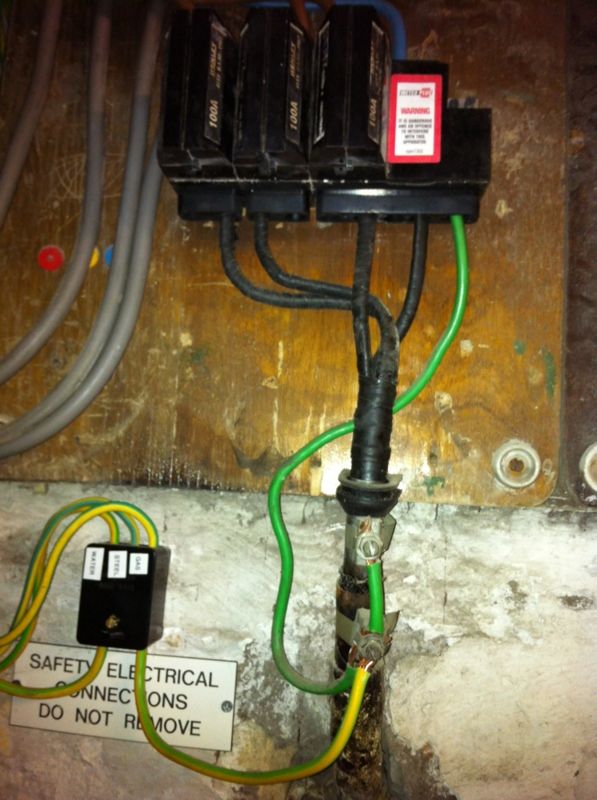
Came across this supply today. Ze is 0.46Ω


2.1 ENA Engineering Recommendation P23/1 gives Guidance relating to Consumers Earth Fault Protection and advice required from Public Electricity Supply Companies.
2.2 Within this document are published suggested maximum values of Earth Loop Impedance (ELI),
primarily for use as a guide to designers of private installations for consideration of their protective devices. The ELI values should allow the service termination fuse to operate within 5s in line with BS7671 and CPxxx.
2.3 In line with these suggested guidance notes **** has adopted the following figures as acceptable values of ELI to be measured at the incoming service termination where an earth terminal has been provided
Non PME System = 0.8 ohm
PME System = 0.35 ohm
(Higher values can be accepted up to 0.8 ohm)
(The value for a PME system being lower as to be expected with the combined neutral / earth configuration)
but not for TN-C-S.
Ah but it is!
The figure of .35 is from a Supply Industry specification going back to the '60s! .35 was a guestimate at the time as it was reasoned that in most cases it would be lower than the .8 figure for TN-s as the neutral and earth were combined.
This figure was included in the regs but only by permission of the supply industry.
But what does the figure actually mean? That a 100A cut out fuse will operate within 5s for a live to neutral or earth fault prior to the first set of customer protective devices.
From one of our documents
2.1 ENA Engineering Recommendation P23/1 gives Guidance relating to Consumers Earth Fault Protection and advice required from Public Electricity Supply Companies.
2.2 Within this document are published suggested maximum values of Earth Loop Impedance (ELI),
primarily for use as a guide to designers of private installations for consideration of their protective devices. The ELI values should allow the service termination fuse to operate within 5s in line with BS7671 and CPxxx.
2.3 In line with these suggested guidance notes **** has adopted the following figures as acceptable values of ELI to be measured at the incoming service termination where an earth terminal has been provided
Non PME System = 0.8 ohm
PME System = 0.35 ohm
(Higher values can be accepted up to 0.8 ohm)
(The value for a PME system being lower as to be expected with the combined neutral / earth configuration)
So .35/.8 is not cast in stone and should be treated as such. We can accept higher values than .8 on a temporary basis by reducing fuse size or ensuring an RCD is fitted immediately after the cutout whilst the situation is rectified
Exactly the same as the standard line-to-earth loop impedance test (i.e. Earth Fault Loop Impedance), but with the test 'short' applied between line and neutral (rather than between line and earth) - i.e. a L-N fault Loop Impedence.Could you expand on the line to neutral loop test please
This L-N will give you the PSCC as L-E gives you PEFC.Could you expand on the line to neutral loop test please
In the absence of supply-side faults, do you ever see PEFC>PSCC?This L-N will give you the PSCC as L-E gives you PEFC. The greater of which is the PFC.Could you expand on the line to neutral loop test please
If you need to find a tradesperson to get your job done, please try our local search below, or if you are doing it yourself you can find suppliers local to you.
Select the supplier or trade you require, enter your location to begin your search.
Are you a trade or supplier? You can create your listing free at DIYnot Local
