Wiring 2 Bell Boxes - One New, One Old with no wiring labels

Joined
24 Jul 2008
Messages
3
Reaction score
0
Location
Lancashire
Country
United Kingdom
Hi-

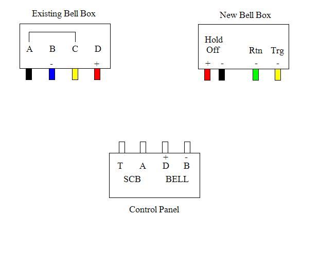
First post here. I have just wired in an Accenta G3 panel in place of my old A&G Premier which had fallen to bits, plus we have extended the house and I wanted to incorporate the new rooms. I have also put a new bell box on the back of the house as well as the old one at the front. This is where I have come unstuck, as although the new bell box appears relatively simple to wire, the old one shows a distinct lack of what each wire is - just A, B, C and D. I have looked at other posts and the alarm sticky post about wiring two bell boxes so I know about the tamper return of the first box being used to supply the second box, but I'm a bit at sea as I don't know which one is which apart from D obviously being the 12V+.

The old panel didn't give anything away either I'm afraid. I've done a diagram below to demonstrate what is written on each component. Can anyone help me please?


Many thanks!

Paul.[/img]
 
Sponsored Links
I havent seen an A & G for years.

the bes way is to put 12v on the bell, and see what it does.

if i recal A+ D were 12v C was return B was ringer, but i may be wrong
 
A = Negative Hold Off (Charging)
B = Negative Bell Trigger
C = POSITIVE Anti Tamper Return
D = Positive Hold Off (Charging)

Have fun
 
i must have a good memeory then (except for th +ve return, dont remember that, but i am not disagreeing)
 
Sponsored Links
Thanks for that. Will hopefully be doing this Monday if the weather stays ok so will let you know how I get on!

Cheers

Paul.
 
At face value you might not be able to use these two boxes together

So I wouldnt recommend doing anything until you have first verified what you do and dont have and what can or cant be altered

The normal and most common bell box configuration is

A = + Supply/Bell +
B = - Trigger/Trig/Trg Bell -
C = Tamper return. This is usually negative, but some can be set to either positive or negative
D = -Supply/ 0V

And then theres usually your STB -/Strobe - connection or on some panels you have a strobe + and - that need to be connected/linked as requirements


To connect two using that configuration the Permanent + and the switched - (trg) will be common to both boxes but the tamper will usually need to be cascaded through both boxes as the feed for the tamper is internally connected to the switch and the monitoring is done between the two connections

So you would take the permanent 0v to the Ov terminal (D) of the first box then the tamper return you connect to the 0v of the second box and that bell boxes tamper return then goes to the control panels tamper return

This does mean that if the lid of the first box is removed the second one will start to sound due to its negative being removed

But as you usually have at least one spare wire in a six core cable anyway the last wire can be used to add a temporary negative from the panel for just that type of occassion when an alarm is installed plus some of the newer bell boxes can be put into their initial silent engineer mode state from the control panel allowing the removal of power or the lid without activation

Looking at your pictures the existing one is a non intelligent box so removal of the link from A to C means the tamper

In your current example what I would have expected is actually this

BB Panel Polarity

A D + supply
B B Switched -
C T - return via the tamper switch
D A - supply

So matching terminals across the system would be (I think)

BB Panel Polarity New

A D + supply Hold off +
B B Switched - TRG -
C T - return via the tamper switch RTN -
D A - supply Hold off -


But that is based on "assuming" the existing box is a positive fed tamper but it could be some other strange variant

Its also worth noting that many new bell boxes wont sound if you only apply the + A and - B signals (+ Hold off and - TRG) because they first need the electronics on the board to be powered up which requires the -D/- hold off to be applied as well as the trigger signal for them to work

I would suggest finding out EXACTLY what the ABC and D terminals in the existing box are and whether they have any other labels or descriptions

The name/make of the box would also be worth a shot I guess

Because if you connect a positive and negative tamper circuit together they will blow the fuse

Although I cant recall ever seeing a domestic panel that supplied a positive tamper to a bell box tbh

I hope some of this was useful
 
Long post that to answer a FOUR YEAR OLD THREAD.

I expect the work has been done by now!
 
I would kind of hope so really lol

But if I found it so might other people as it STILL comes up on google searches and is therefore still ethereally relevant ;)
 
Yes the work was done (4 years ago!) and I sort of got it to work but for some obscure reason the strobe wouldn't function - the bell was fine though.

Took me ages but please don't ask me how I did it...I've slept quite a lot since then...

Cheers

Paul.
 

DIYnot Local

Staff member

If you need to find a tradesperson to get your job done, please try our local search below, or if you are doing it yourself you can find suppliers local to you.

Select the supplier or trade you require, enter your location to begin your search.


Are you a trade or supplier? You can create your listing free at DIYnot Local

 
Sponsored Links
Back
Top