

Hi,
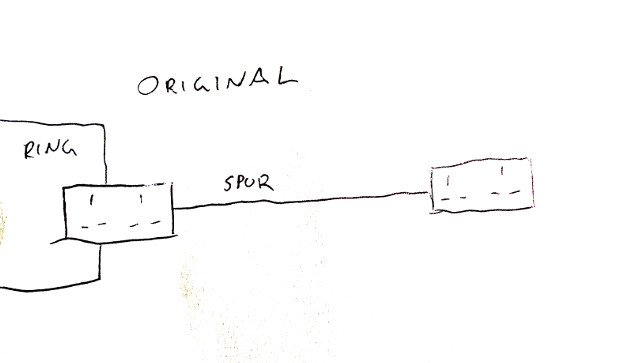
My house was built last year and came with a double socket in the garage, on a spur connected through the wall to the kitchen (see "original" below).
I wanted to add more sockets to the garage for convenience, but don't need any extra power, so I'm limiting the whole garage to 13A through an FCU (originally I had a breaker as per an earlier post, but the electrician didn't like it so I went for the more standard FCU).
I've added 7 sockets (I know its a lot, but they're in convenient places) but I've only drawn 4 in the diagrams for simplicity. All wiring, including before/after FCU, is 2.5mm T&E.
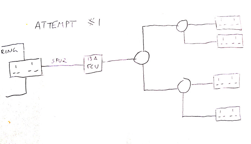
I had an electrician look at what I've done. However he did not like how I had wired up the sockets, see "attempt #1" below, which was using multiple junction boxes branching off in a non-radial arrangement. I believed that the 13A FCU meant I could wire it up however I like, but he said it had to be radial.
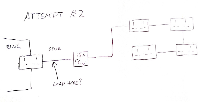
So I went for "attempt #2" below, which is fully radial. The whole length of the spur is as a result almost 30m, which means I think I could see up to 7V voltage drop based on 2.5mm T&E ratings (0.018 x 13A x 30m = 7V). But that should be within limits, I think.
However, the electrician now says he is concerned that because "the fused spur is fed radial from a socket & not wired directly to form part of the ring final" then "the load at the first part of the circuit from skt to spur could exceed the rating of the cable supplying it", and he needs to go and do some calculations.
This seems really odd to me. The load to the FCU will be the same as the load after it, right? And a single spur with double socket or FCU off one point in the ring is totally standard, isn't it?
So my two questions for any electricians who might read this:
1) Was he right that I had to change the wiring on this fused spur from branching junction boxes to completely radial.
2) Why would there now be a problem with load between the ring and the FCU? What is he actually needing to calculate here?
Thanks in advance for any input.
My house was built last year and came with a double socket in the garage, on a spur connected through the wall to the kitchen (see "original" below).
I wanted to add more sockets to the garage for convenience, but don't need any extra power, so I'm limiting the whole garage to 13A through an FCU (originally I had a breaker as per an earlier post, but the electrician didn't like it so I went for the more standard FCU).
I've added 7 sockets (I know its a lot, but they're in convenient places) but I've only drawn 4 in the diagrams for simplicity. All wiring, including before/after FCU, is 2.5mm T&E.
I had an electrician look at what I've done. However he did not like how I had wired up the sockets, see "attempt #1" below, which was using multiple junction boxes branching off in a non-radial arrangement. I believed that the 13A FCU meant I could wire it up however I like, but he said it had to be radial.
So I went for "attempt #2" below, which is fully radial. The whole length of the spur is as a result almost 30m, which means I think I could see up to 7V voltage drop based on 2.5mm T&E ratings (0.018 x 13A x 30m = 7V). But that should be within limits, I think.
However, the electrician now says he is concerned that because "the fused spur is fed radial from a socket & not wired directly to form part of the ring final" then "the load at the first part of the circuit from skt to spur could exceed the rating of the cable supplying it", and he needs to go and do some calculations.
This seems really odd to me. The load to the FCU will be the same as the load after it, right? And a single spur with double socket or FCU off one point in the ring is totally standard, isn't it?
So my two questions for any electricians who might read this:
1) Was he right that I had to change the wiring on this fused spur from branching junction boxes to completely radial.
2) Why would there now be a problem with load between the ring and the FCU? What is he actually needing to calculate here?
Thanks in advance for any input.
Last edited:
