Wiring of trigger circuit for cordless drill

R

richard7761

Can anyone explain in basic terms how this trigger circuit works?

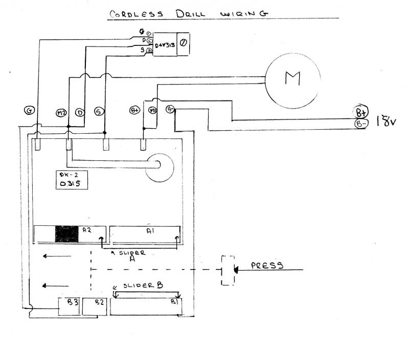
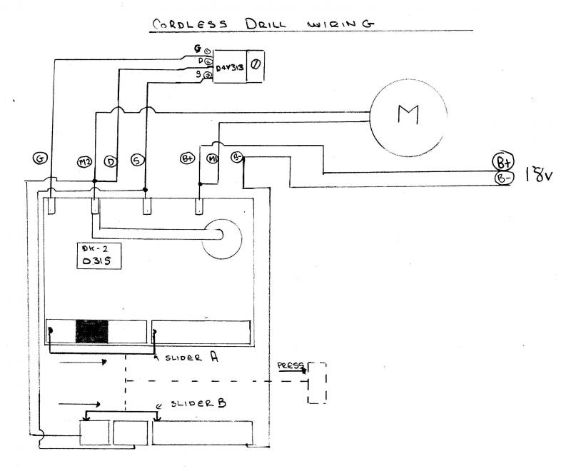
Slider A and B, (pointed out at bottom left in the trigger circuit wiring diagram) represent two sliding contacts. I believe I have it right and that their current position would be the off position. When the drill trigger is pressed, the sliders would go to the right.

Slider A: Contacts two "plates" The dark band on the one on the left plate is I believe a resistance. The right plate is just a piece of metal.

Slider B: The slider contacts metal plates, of which there are three, as shown.

Slider A and B move together.

Anyway, you see that what the sliders contact changes as the sliders move to the right.

A long shot, but can anyone shed any light as to what is happening as sliders move to the right.

The D4v313 component at the top of the wiring circuit is a power mosfet.

Thanks.

159000_158472_30367_91153630_thumb.jpg


Sponsored Links
I'm not sure there is much to say, but I know slider A and the contacts it makes, is really small rheostat.

Slider B is just some switch arrangement. Not sure what it is switching though.
 
As you pull the trigger a small current will go into the switch and across the rheostat. The more you pull the trigger the less resistance. This has to be amplified by the mosfet otherwise the rheostat would burn out with a lot of current passing through it.
A mosfet will cause a small voltage drop and produce heat even at full load and therefore the last part of the trigger action will just connect the supply voltage directly to the output of the mosfet to increase maximum power and heat generated.
 
The part on your drawing marked B could be just a switch for day a small led light on the drill (assuming it has one) Part A is definitely the variable resistance for speed control. ;) ;)
 
Sponsored Links
Slider A definitely is the fundamental variable-speed element to this circuit.

You see that power (B-) to everything goes through slider B, which is acting as a simple kind of switch.

I'm not entirely sure but if the sliders should be positioned to the right, and that when the trigger was pushed sliders go from right to left, opposite to what I've drawn. I never noted the at rest position of the slider, when I took the trigger apart.

Tomorrow I will see if when slider B is to the right, whether B- power is cut off from the left and middle slider B contacts. If so, when initially pressing the trigger, B- is put on the middle contact, then further pressing of trigger puts B- on the end contact (the contact point on the left). That could be the correct situation, but don't know just yet.

No light was on the drill.
 
This picture will be the correctly drawn circuit:

At rest there is no B- to anything. Pressing connects B1 to B2 on slider B. Slider A connects A1 to the resistive portion of A2.

For full speed, B1 connects to B3, and at this position battery voltage goes direct to M.

I think M's speed will be controlled by Pulse Width Modulation, until, that is, the trigger is fully depressed.

[/img]
 

DIYnot Local

Staff member

If you need to find a tradesperson to get your job done, please try our local search below, or if you are doing it yourself you can find suppliers local to you.

Select the supplier or trade you require, enter your location to begin your search.


Are you a trade or supplier? You can create your listing free at DIYnot Local

 
Back
Top