
You are using an out of date browser. It may not display this or other websites correctly.
You should upgrade or use an alternative browser.
You should upgrade or use an alternative browser.
worcester r35he plus s plan wiring problem
- Thread starter davewyorks
- Start date

Sponsored Links
Excellent, diagram would greatly be appreciated cheers mattHi dave you can still feed the roomstat and ufh controller with Ls but leave the link in place
remove the tr2, bridge out the terminals with suitable resistors as per your post above then use the valves end switches to bridge out the 2.2 resistor
I will do a diagram later if req as taxis due now
Matt

ok here is a quick diagram, top using voltfree, bottom using a switched live and a relay as Picasso has suggested. which may be the option for you as you have a switched live there already but you will have to replace the link
View media item 47979
There are a few different ways you could wire this with a relay, but I have shown it with a single pole switch as it works the same way as the voltfree version by basically shorting out the 2.2k resistor when you need a call for heat as per "oldgeeza's" design in the thread you mentioned I've also used the same resistor values as him as I presume it's a tried and tested design, other values may be better,(anyone got a tr2 schematic?)
It will probably easier to wire the resistors to a "choc block" first as shown
A quick word about the Tr2, as mentioned by picasso the Tr2 contains a thermistor which provides feedback to the boiler
The boiler uses this feedback to display the temp and to decide when to switch on/off But it may use this feed back to decide when/how to modulate
if it does (I would have thought so) then the boiler will be less efficient by taking the Tr2 out, but its an optional extra anyway and as you say changng the boiler isn't an option.
I might have a go designing a circuiit that makes use of the tr2 also if I have time
Matt
Hi matt thank you for the diagram, wired as shown in top illustration using the grey and orange from either two port valves to short circuit the 2.2k resistor, everything fine to start with, boiler showing room temp 11 degrees required temp 5 degrees, when call for heat made either zone valve opens required temp goes to 18 degrees boiler runs and fires however take away call for heat, valve closes required temp remains 18 degrees boiler doesn't stop running, only way to get required temp back to 5 degrees is disconnecting resistors making A8 code flash (comunication with stat lost) then re connecting again, scratching head again mateok here is a quick diagram, top using voltfree, bottom using a switched live and a relay as Picasso has suggested. which may be the option for you as you have a switched live there already but you will have to replace the link
View media item 47979
There are a few different ways you could wire this with a relay, but I have shown it with a single pole switch as it works the same way as the voltfree version by basically shorting out the 2.2k resistor when you need a call for heat as per "oldgeeza's" design in the thread you mentioned I've also used the same resistor values as him as I presume it's a tried and tested design, other values may be better,(anyone got a tr2 schematic?)
It will probably easier to wire the resistors to a "choc block" first as shown
A quick word about the Tr2, as mentioned by picasso the Tr2 contains a thermistor which provides feedback to the boiler
The boiler uses this feedback to display the temp and to decide when to switch on/off But it may use this feed back to decide when/how to modulate
if it does (I would have thought so) then the boiler will be less efficient by taking the Tr2 out, but its an optional extra anyway and as you say changng the boiler isn't an option.
I might have a go designing a circuiit that makes use of the tr2 also if I have time
Matt
Sponsored Links
Hi dave
sorry to hear things ddn't work out, as I said earler the drawing I did was based on using the same workaround that "oldgeezer" used n the post you made
I find it strange that the call for 18 degrees stays the same when you put the 2,2k resistor back into circuit though so I would check the external wiring
A quick check would be to make a call for heat via the zone valves then physically pulling either one of the switch wires out of the resistor network connector block if you have wired it the same as my drawing
if the heating demand then stops, then its a problem with the wiring
if the demand stays as it is on 18 then it's back to the drawing board
However I did a bit more digging and found this, (credit to a fella called Craig Nixon)
He didnt actually post a drawing but based on the above then it should be something like this...........(edit....now updated see next page)
View media item 48031
if you could post some photos of the pcb dave (both sides) it would be useful
as better options may be available as I think we may still be able to incorperate the tr2 in part
Matt
sorry to hear things ddn't work out, as I said earler the drawing I did was based on using the same workaround that "oldgeezer" used n the post you made
I find it strange that the call for 18 degrees stays the same when you put the 2,2k resistor back into circuit though so I would check the external wiring
A quick check would be to make a call for heat via the zone valves then physically pulling either one of the switch wires out of the resistor network connector block if you have wired it the same as my drawing
if the heating demand then stops, then its a problem with the wiring
if the demand stays as it is on 18 then it's back to the drawing board
However I did a bit more digging and found this, (credit to a fella called Craig Nixon)
I have similar problem with this
boiler and have reverse engineered the TR2 interface (bit of an
exageration for what it is). I came up with what now seems an overly
complex solution which fooled the boiler into thinking the tr2 was a) in
constant mode and b) demanding max heat. this is done by inserting an
8.95 kohm (a standard 9.1kohm should still work) resistor across pins 4
& 3 of the tr2. The tr2 presents a resistance (my actual measured) to
the boiler based on the demand temperature on the rotary dial and the
position of the 4 position switch as follows:
switch position 30Deg .............0Deg
constant 8.95 kohm 11.27
timed 6.22k 8.54k
night(econ) 13.96k
frost 12.64
From observation of the pcb the rotory dial is a 2.2k pot. in series
with a 6.2k (3.5k +2.7k) and a 2.7k which is switched in for constant
(i.e un timed operation. it is worth noting that the pot is low for high
temp demand and 2.2k for low temp (confused me for a minute did that).
The night and frost are fixed 14k and 12.7k resistors.
He didnt actually post a drawing but based on the above then it should be something like this...........(edit....now updated see next page)
View media item 48031
if you could post some photos of the pcb dave (both sides) it would be useful
as better options may be available as I think we may still be able to incorperate the tr2 in part
Matt
A quick check would be to make a call for heat via the zone valves then physically pulling either one of the switch wires out of the resistor network connector block if you have wired it the same as my drawing
if the heating demand then stops, then its a problem with the wiring
if the demand stays as it is on 18 then it's back to the drawing board
Hi matt did check external wiring just as above, also removed wires altogether and manually called for heat by linking the 2.2 resistor out with a piece of wire only to have same result i.e room temp stays 18 degrees when link removed, also checked resistors with meter they ok, will take photos as soon can do, very appreciative for your help matt
Hi dave, just a quick thought
check to see if the boiler is in eco mode, if it is, turn eco off then try the test again.
Matt
check to see if the boiler is in eco mode, if it is, turn eco off then try the test again.
Matt
Hi matt tried boiler in every mode, set eco temp 5 degree then set clock to constant eco mode, also set timeclock to constant (comfort) to no avail, noticed when boiler showing room temp 11degrees, that time clock also stipulated frost mode activated in manual mode, did wonder if down to inferior resistors whilst scratching headHi dave, just a quick thought
check to see if the boiler is in eco mode, if it is, turn eco off then try the test again.
Matt
Hi matt tried boiler in every mode, set eco temp 5 degree then set clock to constant eco mode, also set timeclock to constant (comfort) to no avail, noticed when boiler showing room temp 11degrees, that time clock also stipulated frost mode activated in manual mode, did wonder if down to inferior resistors whilst scratching head
Hi dave as I see it the timer should have no effect because off the values of resistors used (10k+2.2k)
when the two are in series then the boiler "sees" that the tr2 is in manual frost mode
when the 2.2k is shorted out then the boiler takes this (10k) as the tr2 in constant on mode (hence the timer not having any effect) and asking for around 18 degrees
the boiler will always see 11 degrees because of the 3.3k resistor taking the place of the tr2's thermistor (we could also use this to potentially switch the boiler on/off)
in summary,the boler looks at the resistance presented between pins 3 and 4 and changes mode accordingly, so
14k = constant off/eco mode
12.7k = frost manual mode
8.9k to 11.1k constant on mode (temp req dependant on value)
6.2k to 8.4k auto/timer mode (temp req dependant on value)
as you can see the resistance values are pretty tight, but again all this is based on third party observations so I will look forward to any photos you can post
Matt
One thing that I dont understand (more than one really) is that as far as I know the intergrated timer does not use any sort of bridge if the tr2 is disconnected, does that mean if the boiler "sees" no resistance it runs constantly?
Hi picasso yes with the tr2 removed the boiler runs constant, with the ability to switch between comfort and eco via the integrated time clock.One thing that I dont understand (more than one really) is that as far as I know the intergrated timer does not use any sort of bridge if the tr2 is disconnected, does that mean if the boiler "sees" no resistance it runs constantly?
Hi picasso yes with the tr2 removed the boiler runs constant, with the ability to switch between comfort and eco via the integrated time clock.One thing that I dont understand (more than one really) is that as far as I know the intergrated timer does not use any sort of bridge if the tr2 is disconnected, does that mean if the boiler "sees" no resistance it runs constantly?
Hi picasso, what's the other ones?
I dont understand a few things either, like how this seemed to work for oldgeeza but not for dave, differing boiler software or a parameter setting maybe
but there will be a workaround I'm sure even if it means changing the control system slightly
still reckon the tr2 could be used in too
Matt
Yea "oldgeezas" stat working and yours not was one of the things, one of the others was if we simply want the boiler to switch on/off couldent the resistor value be used for "off" and simply disconnected to bring the boiler on full, or is that not gonna work ?
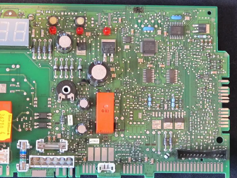
if you could post some photos of the pcb dave (both sides) it would be useful
as better options may be available as I think we may still be able to incorperate the tr2 in part
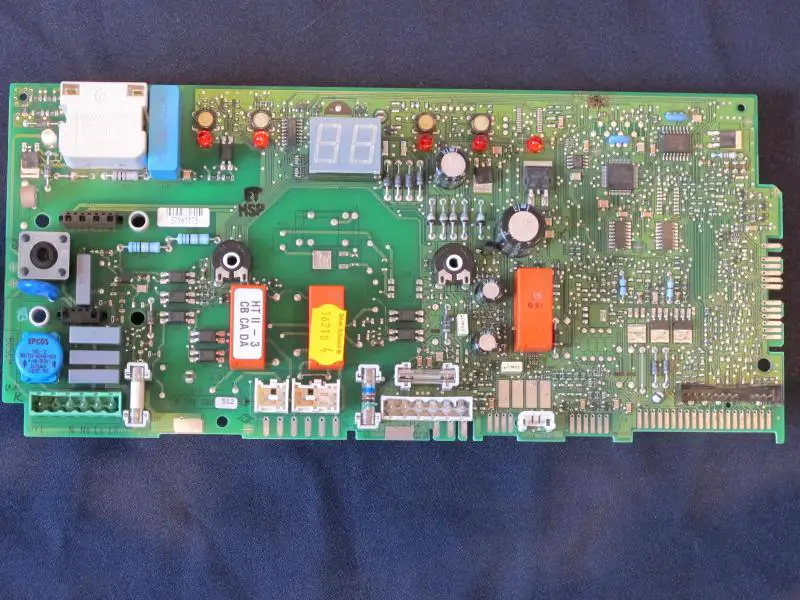
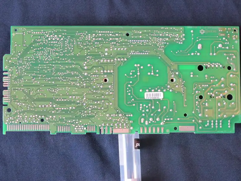
Matt[/quote] Hi matt managed some photos hope you can make head or tail with them,ht//media.diynot.com/191000_190175_48099_42896035_thumb.jpgtp://m//media.diynot.com/191000_190175_48100_29973100_thumb.jpgedia.diynot.com/1http://media.diynot.com/191000_190175_48101_35144673_thumb.jpg91000_1901//media.diynot.com/191000_190175_48102_26691439_thumb.jpg75_48098_39055013_thumb.jpg [/img]
as better options may be available as I think we may still be able to incorperate the tr2 in part
Matt[/quote] Hi matt managed some photos hope you can make head or tail with them,ht//media.diynot.com/191000_190175_48099_42896035_thumb.jpgtp://m//media.diynot.com/191000_190175_48100_29973100_thumb.jpgedia.diynot.com/1http://media.diynot.com/191000_190175_48101_35144673_thumb.jpg91000_1901//media.diynot.com/191000_190175_48102_26691439_thumb.jpg75_48098_39055013_thumb.jpg [/img]
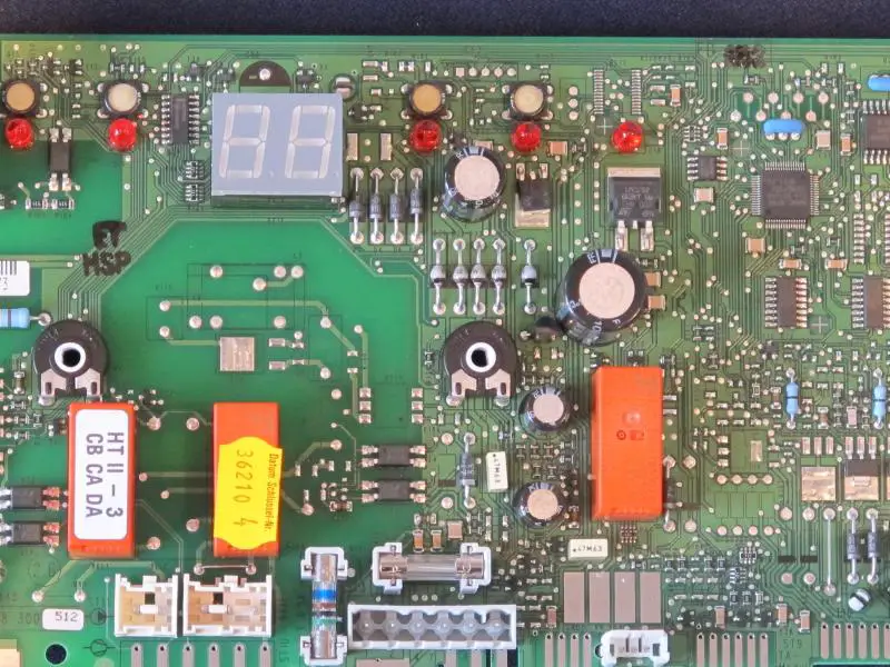
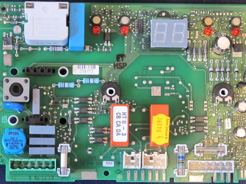
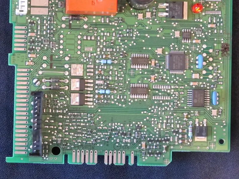
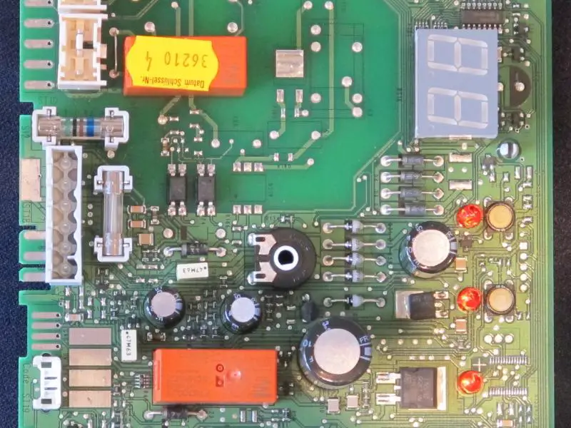
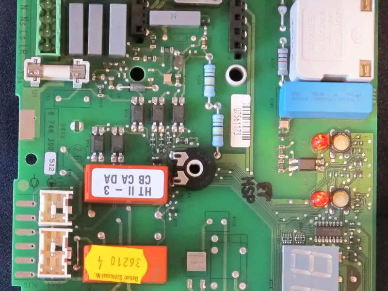
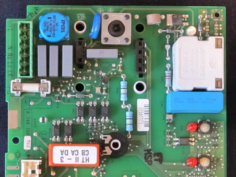
davewyorks";p="2452189 said:if you could post some photos of the pcb dave (both sides) it would be useful
as better options may be available as I think we may still be able to incorperate the tr2 in part
Try again


DIYnot Local
Staff member
If you need to find a tradesperson to get your job done, please try our local search below, or if you are doing it yourself you can find suppliers local to you.
Select the supplier or trade you require, enter your location to begin your search.
Please select a service and enter a location to continue...
Are you a trade or supplier? You can create your listing free at DIYnot Local
Sponsored Links
Similar threads
- Replies
- 2
- Views
- 2K
- Replies
- 21
- Views
- 9K
- Replies
- 0
- Views
- 410
- Replies
- 0
- Views
- 483
- Replies
- 1
- Views
- 596
