Data Logger

Joined
21 May 2010
Messages
10,194
Reaction score
2,913
Location
Northamptonshire
Country
United Kingdom
This is an 8 Chanel data logger that generically measures temps with thermocouples (I am heating engineer) that I use regularly. I have an issue where It would be really handy to also check on 2 x 220v switches that they are in fact switching, on a swimming pool complex. They advertise an adaptor to measure small current & small voltage. What do I need to do / buy to make this work for 220 volts please?

The pico data logger has these adaptors for measuring current & voltage.
https://www.picotech.com/data-logger/tc-08/thermocouple-data-logger
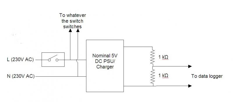
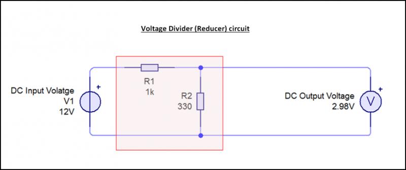
 
Sponsored Links
Th simplest solution would probably be to connect a small low voltage (5V or less) DC power supply (phone charger?) to the switched output of each of the switches of interest and use the data logger to monitor the (low voltage DC) output of those power supplies.

Kind Regards, Johne
 
Th simplest solution would probably be to connect a small low voltage (5V or less) DC power supply (phone charger?) to the switched output of each of the switches of interest and use the data logger to monitor the (low voltage DC) output of those power supplies.

Kind Regards, Johne
I love clever simple ideas! Thanks will they be 5 volts with virtually no load on them? My limited experience of chargers is the open cct voltages are very varied?
 
Th simplest solution would probably be to connect a small low voltage (5V or less) DC power supply (phone charger?) to the switched output of each of the switches of interest and use the data logger to monitor the (low voltage DC) output of those power supplies.
I love clever simple ideas! Thanks will they be 5 volts with virtually no load on them? My limited experience of chargers is the open cct voltages are very varied?
Yes, you need to watch that -you want something that produces no more than 5V off-load. However,if you're prepared to play with a couple of resistors, you could put them in series across the "5V" output and use them as a voltage divider to reduce the voltage to something that was definitely under 5V, even when essentially off-load - e.g. if you put a couple of,say, 1kΩ resistors in series across the PSU/charger output, the voltage across one of those resistors would be half of whatever voltage was coming out of the device.

Kind Regards, John
 
Sponsored Links
right so I have a ratio of 220 - 5 = 44:1 so if i put a 43ohm in series with a 1 ohm & put 220 across them both but take the 5v across the 1 ohm I am there in principle? Does the +/- 5v suggest AC or either 5v+ or 5v-?
 
right so I have a ratio of 220 - 5 = 44:1 so if i put a 43ohm in series with a 1 ohm & put 220 across them both but take the 5v across the 1 ohm I am there in principle? Does the +/- 5v suggest AC or either 5v+ or 5v-?
You''re going a bit wrong there. For a start, I presume that the +/- 5V for the data logger adaptor is talking about DC (i.e. from -5V to +5V DC). Secondly, forget about the ratio of the power supply - the 'voltage divider' (resistors) needs to be applied to the output of the power supply ...

... so, say, if you have a "5V" DC 'charger' which gives, say, 8V off-load, if you did as I said before and put two 1k Ω resistors in series across its (nominally "5V") output, the voltage across one of those resistors would be about 4V (half of 8V), hence fine for your logger. You wouldn't want to use resistors much smaller than that, because they would simply draw an unnecessary amount of current.

Is that clearer?

Kind Regards, John
 
As suggested use a couple of resistors but add an LED between O volts and the mid point of the resistors. This will result in a defined voltage of about 0.7 to 2,1 volts ( depends on the type and colour of the LED ) in the ON state and practically zero in the OFF state.

The smoothing capacitor in the power supply will delay the drop of voltage when the supply is turned OFF. If accurate time measurement is needed then to reduce this delay a low value resistor across the output will be needed to discharge the capacitor quickly
 
Something like ....
Bernard's points of 'added sophistication' are valid, although I suspect that neither of the measures he suggests would actually be necessary for your purpose.

Kind Regards, John
 
What am I missing there are a 1001 chargers on the market to charge USB devices.
Indeed - and the box in the middle of my diagram is one of them :) The OP's concern is that some/many of them have off-load voltages appreciably above 5V, which is apparently the maximum his data logger's adaptor can cope with - hence my suggestion as to how he could reduce (say halve) the output voltage of the charger/PSU if it transpires that the off-load output voltage of whatever he uses is above 5V.

Kind Regards, John
 
What am I missing there are a 1001 chargers on the market to charge USB devices.

I feel eric may think the ops after a charger for the item.

When what your desighning is something to give the unit a signal, at a very low voltage, each time a 240v switch is operated
 
I have an issue where It would be really handy to also check on 2 x 220v switches that they are in fact switching

Do you just want to check the switches are operational?, if so just use a cheap multimeter to measure continuity.

If you want to check and record when they switch on and off, you could do what JohnW2 said. Just make sure it is a DC power supply with a voltage no higher than 5V DC going to the data logger.

You could get this: https://www.tlc-direct.co.uk/Products/SK153753.html and create a voltage divider with a 1k and a 330 ohm 0.6w metal film resistors what you can get from maplins'.

This is how the voltage divider would be wired:

 
What am I missing there are a 1001 chargers on the market to charge USB devices.
I feel eric may think the ops after a charger for the item.
Oh, maybe. Perhaps I should have labelled my diagram "...to data logger signal input" (rather than just"...to data logger") - it goes to show how difficult it can be to anticipate the ways in which one's words may be misinterpreted!
When what your designing is something to give the unit a signal, at a very low voltage, each time a 240v switch is operated
Exactly - will, at least, that's what I was 'designing' - since it's what I understood the OP wanted!

Kind Regards, John
 
Do you just want to check the switches are operational?, if so just use a cheap multimeter to measure continuity.
It is surely apparent from what the OP says (about the 'adapter' for his logger) that he wants his data logger to record the on/off status of the two switches 'continuously'. I also assumed that the switches were switching "220V" loads in the heating system.
If you want to check and record when they switch on and off, you could do what JohnW2 said. Just make sure it is a DC power supply with a voltage no higher than 5V DC going to the data logger.
Indeed - and I've been suggesting one way in which he could achieve that.
You could get this: https://www.tlc-direct.co.uk/Products/SK153753.html and create a voltage divider with a 1k and a 330 ohm 0.6w metal film resistors what you can get from maplins'.
Yep. In fact, if he were buying things from the likes of Maplin, he could probably get a multi-voltage PSU which had a, say, 3V DC option - so would not need any voltage divider.

Kind Regards, John
 
Thank you for your interest in this. A swimming pool is a very slow animal. it takes days to warm and cost effectiveness (gas consumption) on a daily basis is critical. I am trying to check up on the BMS (Boiler Management System) which runs 2 cascading & sequencing boilers. I need to run the test for a week to see if I can see a corresponding drop of temp to a particular function of a set of relays. So a multimeter is not an option as I would need to be there all week including nights.
Listening to your ideas I have found this:

http://cpc.farnell.com/myrra/47122/.../dp/TF01427?in_merch=Products From This Range

Its as cheap as chips & if the right thing I can put 4 in a box along with 4 data logger adapters (as in the original link to the data logger & connect them directly to 4 'K' (thermocouple) inputs on the logger so I can check when if & how long for these relays open & the corresponding change of temp (all be it a good few hours later to notice it :eek: )

If I am reading the spec on these items correctly they look as if they have a reasonably stable 5vDC output? Would u think these suitable?
Again thanks for your suggestions.
edit:
A thought on not running thgis PSU open cct:

Peramiters for this PSU are 5vDC 2.75 W
So W=VxI
2.75 = 5 xI
I= 2.75/5.
=.55 Amps

V=IxR
5=.55 x R
5/.55 = R
R= 9ohms

So if I fit a 9ohm 3watt or larger resistor across th o/p I have given it a load so the voltage should be more accurate than running open cct?

a 20ohm resistor will presumably have it running not tp much with less build up of heat?
 

DIYnot Local

Staff member

If you need to find a tradesperson to get your job done, please try our local search below, or if you are doing it yourself you can find suppliers local to you.

Select the supplier or trade you require, enter your location to begin your search.


Are you a trade or supplier? You can create your listing free at DIYnot Local

 
Sponsored Links
Back
Top