- Joined
- 10 Feb 2024
- Messages
- 6
- Reaction score
- 1
- Country


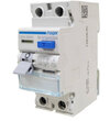
No problem.Can I feed this RCD from the bottom or is strictly the top feed only ?
I think there is one potential problem. ... if one wires it the 'unintended' way around then if one keeps one's finger on the test button, one will rapidly burn out the resistor. Wired.conventionally, the 'test current path' disappears as soon as the device operates.No problem.
I may be very wrong - but from the diagram, I believe the path from the test button is broken from the same mechanism that disconnects the L and N...if one wires it the 'unintended' way around then if one keeps one's finger on the test button, one will rapidly burn out the resistor.
You may well be right, and that would be sensible, but the degree of 'clarity' (or otherwise) in the 'blown-up' diagram you've posted does not enable me to be sure of thatI may be very wrong - but from the diagram, I believe the path from the test button is broken from the same mechanism that disconnects the L and N...
") . However, even if that is true of the one we're looking at (and may even be true of them all 'these days'), I'm pretty sure that, in the past, I've seen ones which have no switching of the test current path, and are therefore presumably susceptible to the issue I mentioned.
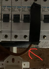
. However, even if that is true of the one we're looking at (and may even be true of them all 'these days'), I'm pretty sure that, in the past, I've seen ones which have no switching of the test current path, and are therefore presumably susceptible to the issue I mentioned.It could, but I would suspect that, since the question is being asked, the OP is probably not talking about installing it in a conventional CU.Although, could connecting it from the bottom cause issues with bus bars?
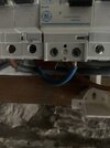
It’s being installed in a older Hager board , the old GE RCD is being supplied from the breaker beside it with a little bus bar link from the non RCD side of the boardYou may well be right, and that would be sensible, but the degree of 'clarity' (or otherwise) in the 'blown-up' diagram you've posted does not enable me to be sure of that
It could, but I would suspect that, since the question is being asked, the OP is probably not talking about installing it in a conventional CU.
Kind Regards, John
That's obviously the sort of issue I was referring to.On older units I've seen the test circuits have been one wire from each side of the main contacts.
The issue with that being continued operation of the button could potentially supply 'test current' to the load side.
Fair enough - I acknowledged that as a possibility when I wrote:I believe they are all made as shown now.
Kind Regards, John..... However, even if that is true of the one we're looking at (and may even be true of them all 'these days'), I'm pretty sure that, in the past, I've seen ones which have no switching of the test current path, and are therefore presumably susceptible to the issue I mentioned.
It might well make the wiring easier, but it would mean that the operating lever would then be "down for on", which some people might regard as undesirable and a potential 'hazard'.Is it being fitted in an enclosure with other modules or on its own? If solo could you mount it upside down, not convential but might make your wiring easier.
If you need to find a tradesperson to get your job done, please try our local search below, or if you are doing it yourself you can find suppliers local to you.
Select the supplier or trade you require, enter your location to begin your search.
Are you a trade or supplier? You can create your listing free at DIYnot Local