Diagram for finding a fault on a ring main

Joined
22 Sep 2007
Messages
16
Reaction score
0
Location
Bristol
Country
United Kingdom
Does anyone have a diagram (or know where one can be found) showing how to perform a test to determine the location of a fault within the damaged cable of a ring-main?
For example: When carrying out an insulation resistance test between 'live' conductors of the socket outlet circuit, a short circuit is discovered.
 
Sponsored Links
What do you mean when you saying a short circuit?
Is it a low reading? when you turn on the circuit does it blow?
How were the other tests; continuity (R1+R2 and R1+Rn)), Continuity of R1, R2 and Rn. Sometimes you will get a very low IR reading although the circuit is ok, the reason, in most cases, (not always) would be a load connected somewhere.
 
I'm just looking for the answer to my original post.
It is a hypothetical question.
Thanks
 
Sponsored Links
Yes, Lectrician.........you're right!
Sorry to sound thick, but I can't seem to get my head around this.
It's probably so easy, that's why I was asking for a diagram on how to test for this senario.
 
Here it is (theoretically) - the half split method

If you have a ring with 8 sockets on it what you do is split the ring between the 4th and 5th socket and test each leg (only 1 should show a fault). Now split the faulty side in half and test both of those legs, keep on splitting until you have found the fault.

Just remember in the real world that you could also have a fault with the socket outlet it's self.

Hope this helps
 
Its not unknow to have a fault on both halves of the ring, which will leave you scratching you head for quite a while.
 
nozspark said:
Here it is (theoretically) - the half split method

........(only 1 should show a fault)...........

As this is a college question it would be rather harsh of the tutor to expect them to find more than one fault... and I did say "should"
 
Nozspark, thanks for that, however, I still can't visulise how to do this. That's why I was hoping for a diagram, and I have to explain this with the aid of a diagram.
 
Not a very goo picture, but here goes

ring.jpg


Firstly I would draw a line through socket 4 and say that I'd split the ring at that point and test at that point (ring left open ended at CU)

Now lets say that after testing that the leg with sockets 5,6,7 & 8 were fault free, but the leg with sockets 1,2 & 3 had a fault

Now I would split the ring at socket 2 and test from socket 2 position

lets say the leg with socket 3 on it had a fault, but the leg with socket 1 on didn't

Now you know that the fault is on a cable connected to socket 3, so you disconnect at that socket and test from that point.

Now the cable which has the fault is faulty and once replaced you can refit all the sockets you removed and test the ring again, just to make sure
 
It looks like Nozspark has beaten me to it, but my diagrams are better :LOL:


RingCCT3.jpg


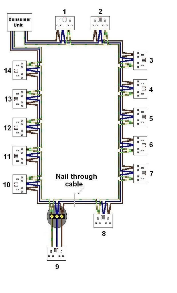
This is a typical ring with a fault on it causing a short between live and earth (for example)

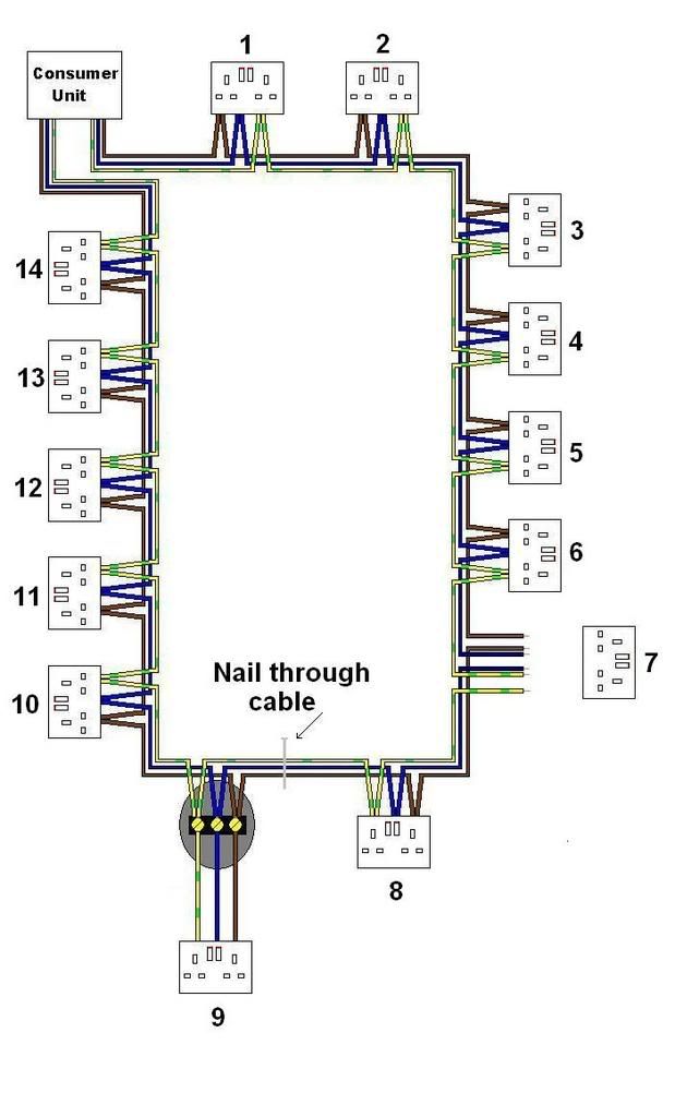
The first thing to do is split the ring at the mid point (or as close as you can get)

The mid point of this ring is socket 7, so you would remove that socket front making sure all of the wires are seperate.


RingCCT2.jpg


Then test each leg of the ring at the CU. It will show that the right leg of the ring is ok, and the fault is on the left leg, somewhere between the CU and socket 7.

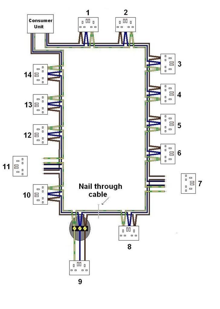
The next thing to do is to split the faulty half of the ring again, which would be at socket 11.


RingCCT4.jpg


Then test the left hand leg from the CU. This will now show no fault, indicating the fault is between sockets 7 and 11. You can test this section of the ring to make sure.

Then split the faulty part of the ring again. In this example it would be at the junction box for socket 9.

then test the section between socket 7 and the junction box, and socket 11 and the junction box.

This will show the fault is between socket 7 and the junction box.

Keep doing this until you have tracked the fault to between two points on the ring circuit. In this example between socket 8 and the junction box for socket 9.

Replace this part of the circuit, put it all back together, and retest everything to make sure the fault has been removed.
 
The other way is.

if you cant find where it IS
then find where it ISN'T

so in the case of a ring you break it down and if its not in one half it must be in the other
 

DIYnot Local

Staff member

If you need to find a tradesperson to get your job done, please try our local search below, or if you are doing it yourself you can find suppliers local to you.

Select the supplier or trade you require, enter your location to begin your search.


Are you a trade or supplier? You can create your listing free at DIYnot Local

 
Sponsored Links
Back
Top