Energy monitor clamp behavior!? (Looping live thru clamp)

Joined
28 Jul 2012
Messages
1,348
Reaction score
55
Location
Surrey
Country
United Kingdom
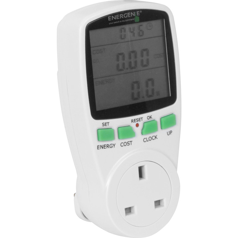
I made a energy test jig yesterday to allow me to easily measure the power of individual items. The photos below show it. :)

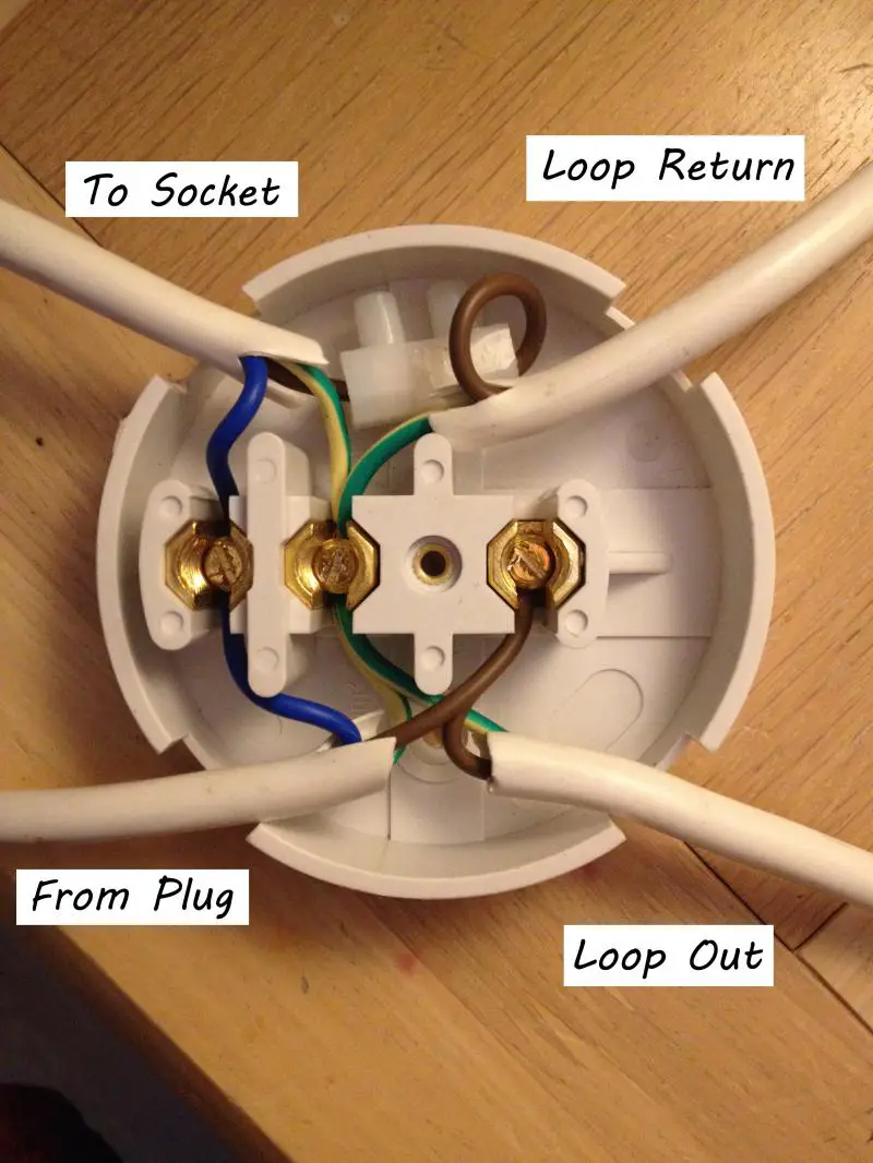
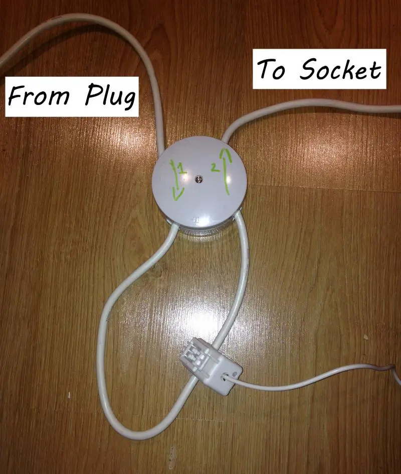
(Current flows from plug, through the loop section and then to socket; the neutral bypasses the loop and goes straight through JB.)
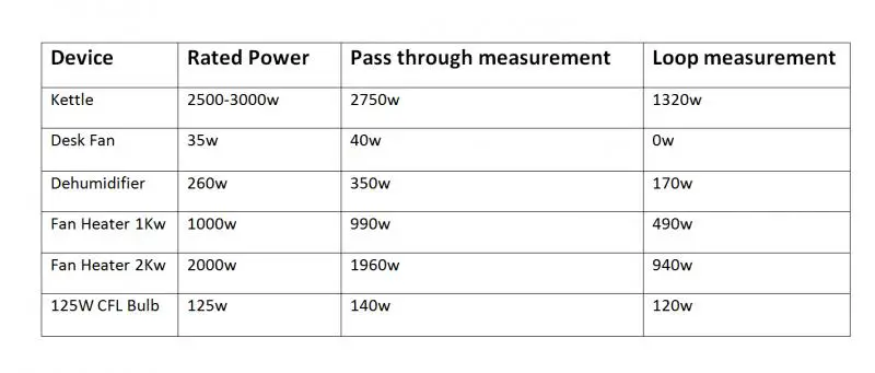
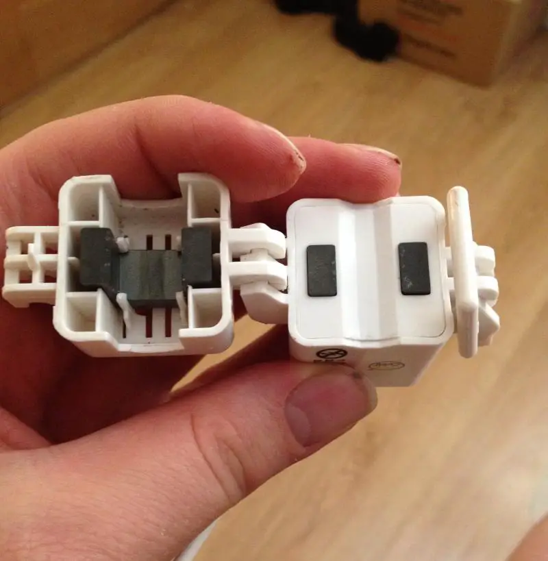
What I can't work out :oops: :?: is why when their is a loop through the clamp as shown in the second photo, the meter reads nothing but when it is a straight pass through the clamp it works fine.

Been a long time since I did anything to do with magnetic fields and electrical currents at school, but if I remember correctly they pass each other at 90 degree angles, although don't suppose that has anything to do with it.

I incorrectly assumed that it would see twice the current because the current was passed through it two times, but somehow I guess the magnetic fields from each pass through the clamp are canceling each other out.

Not sure why they would cancel each other out when the current is flowing in the same direction, but am guessing either it has something to do with the direction of the magnetic fields or some sort of inductance/capacitance effect.

I would be most thankful if anyone who could explain what is happening and illustrate it.

Pictures Below:

No Loop


With Loop


Regards: Elliott[/b]
 
Sponsored Links
With two passes through the sensor you should be reading twice the value that a single pass produces.

Check that with two passes that the clamp is fully closed and that the faces of the magnetic core are touching each other. Even the slightest gap in the magnetic path through the core will reduce the reading to a value approaching zero.
 
Also, your clamp is round the whole cable. This will have the line, neutral and earth conductors in it.

For it to work properly, you need your clamp round the line conductor only.
 
Sponsored Links
I incorrectly assumed that it would see twice the current because the current was passed through it two times, but somehow I guess the magnetic fields from each pass through the clamp are canceling each other out.
As bernard has said, your assumption was essentially correct - so, as he said, something is 'going wrong' with your 'two pass' experiment.

If, as bernard suggested, the problem is that the clamp is not closing properly with two cables in it, you could adjust the wiring within the JB so that you were using two cores within the one cable (making sure to get the directions of current flow the same in both), hence only need the one cable to go through the clamp.

Kind Regards, John
 
it would be interesting to see what's happening inside that junction box
 
Could it be that the clamp is not magnetically shielded, so the field from the loop is cancelling that from the wire within the clamp, or maybe just saturating the clamp sensor?
 
Could it be that the clamp is not magnetically shielded, so the field from the loop is cancelling that from the wire within the clamp, or maybe just saturating the clamp sensor?
Possibly, although that loop is really no more than a two-turn 'winding', which I would have expected to work - but maybe I'm wrong!

However, if the OP did as I suggested, and used two cores of the cable, suitably wired so that the same current flowed in the same direction in both, that cable would only have to make a single pass through the sensor.

Kind Regards, John
 
it would be interesting to see what's happening inside that junction box
I think it's fairly obvious from the OP's description, isn't it? ... N and E go straight though (from 'socket' to 'plug'), whilst L goes from 'socket' to 'plug' via one of the cores (or maybe 2/3 cores in parallel) of the 'loop' cable which goes through the sensor.

Kind Regards, John
 
I made a energy test jig yesterday to allow me to easily measure the power of individual items.
Plan A
  • Frat about wiring up plugs, trailing sockets, junction boxes.
  • Use a clamp-on detector known to be unreliable with low loads.
  • Not get it to work properly, and have to take photos and post here.
Plan B

blank_65x10_T.gif
90072.jpg


And Plan A is the easy one?


:confused:
 
Firstly I know the energy clamps are not accurate, especially at low loads, but I built the jig simply because it was what spare bits I had laying around (including the clamp style energy monitor) and I just wanted to experiment and see what sort of results I would get from it.

If I had an individual plug in energy monitor like BAS showed, then I would have used that of course. (And yes, I keep meaning to buy one.)

Also I based my initial results on a 35w desk fan, but I have now tested my rig with several devices of various power ratings and the table below shows the results. Note I kept the clamp setup the same for all the loop measurements and pass through measurements respectively. The loop of cable was also very tight in the clamp in the loop arrangement.


For those interested to see inside the JB, then see the photo below. Forgive me for the non compliant terminal connector inside. :oops:


Also the clamp is the Owl CMR130, see the photo below.


Regards: Elliott
 

DIYnot Local

Staff member

If you need to find a tradesperson to get your job done, please try our local search below, or if you are doing it yourself you can find suppliers local to you.

Select the supplier or trade you require, enter your location to begin your search.


Are you a trade or supplier? You can create your listing free at DIYnot Local

 
Sponsored Links
Back
Top