Hi
I have a Worcester Heatslave combi boiler which has a built in Worcester twin channel programmer. The LCD display has gone blank, but for now the programmer still works.
I plan to replace the twin channel programmer with a new external programmer.
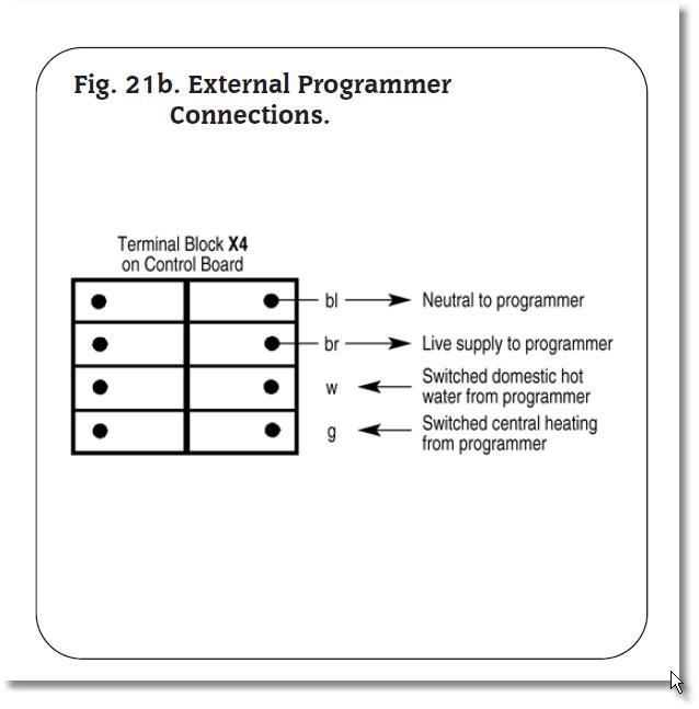
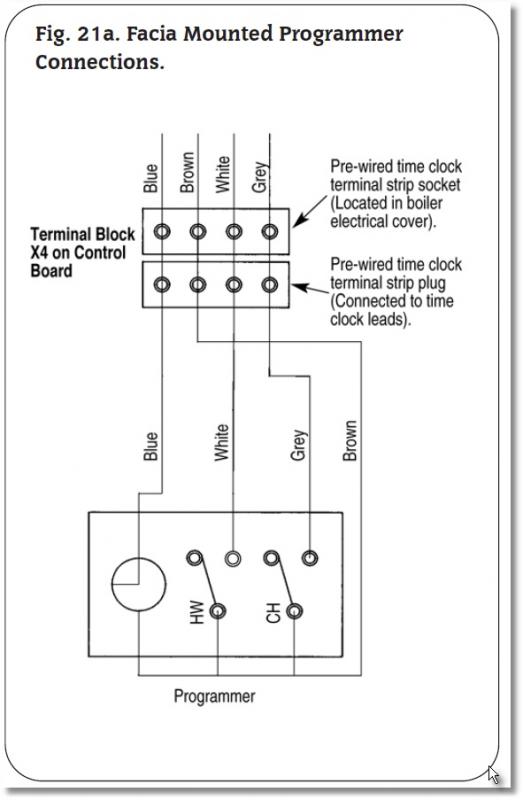
Looking at the installation instructions for the boiler it shows 4 connections for an external programmer - L, N, SL to CH and SL to DHW. Please see the diagrams Facia Mounted Programmer Connections and External Programmer Connections.
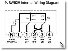
The external programmer I plan to fit is a Siemens RWB29. I have attached a copy of the internal wiring diagram for this programmer.
As I understand it the wiring will be as follows :
The brown wire is L and the blue wire in neutral
The CH On connection ( 4 ) is a Switched Live which will connect to the grey wire at the boiler.
The DHW On connection ( 3 ) is another Switched Live which will connect to the white wire at the boiler.
This makes sense to me. There will be no connections at 1 and 2 on the programmer back plate as these are the OFF positions.
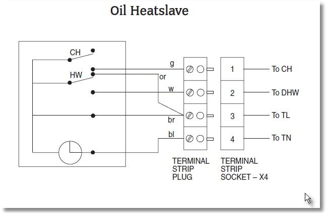
However when I looked at the actual wiring for the existing twin channel worcester programmer I see that there is a 5th ( Orange ) wire ??? Please see diagram Oil Heatslave.
This has me a little confused. Is it something to do with the Pumped or Switched setting on the twin channel programmer ?
Many thanks for any help.
I have a Worcester Heatslave combi boiler which has a built in Worcester twin channel programmer. The LCD display has gone blank, but for now the programmer still works.
I plan to replace the twin channel programmer with a new external programmer.
Looking at the installation instructions for the boiler it shows 4 connections for an external programmer - L, N, SL to CH and SL to DHW. Please see the diagrams Facia Mounted Programmer Connections and External Programmer Connections.
The external programmer I plan to fit is a Siemens RWB29. I have attached a copy of the internal wiring diagram for this programmer.
As I understand it the wiring will be as follows :
The brown wire is L and the blue wire in neutral
The CH On connection ( 4 ) is a Switched Live which will connect to the grey wire at the boiler.
The DHW On connection ( 3 ) is another Switched Live which will connect to the white wire at the boiler.
This makes sense to me. There will be no connections at 1 and 2 on the programmer back plate as these are the OFF positions.
However when I looked at the actual wiring for the existing twin channel worcester programmer I see that there is a 5th ( Orange ) wire ??? Please see diagram Oil Heatslave.
This has me a little confused. Is it something to do with the Pumped or Switched setting on the twin channel programmer ?
Many thanks for any help.