linking existing CH to new UFH system

Joined
1 Oct 2012
Messages
4
Reaction score
0
Location
Essex
Country
United Kingdom
We have the house extended and moved from a Y plan heating system to an S plan system with zones for HW, CH and a new zone for the UFH.
The plumbing side of it is all fine, and the electrical connections for the HW and CH are fine, but I need to connect in the control box for the actuators on the manifold, UFH pump and zone valve.

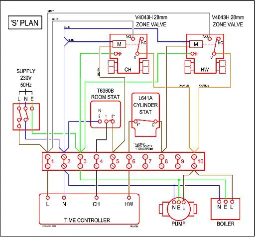
I've got two diagrams, one for an standard S Plan system
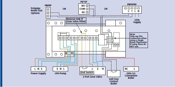
One for the UFH controller

Question is how to link the two.
I think I've concluded that the boiler connection form the bottom right of the UFH diagram needs to go into slot 10 on the connector strip, so it will only come when the programmer says so, and the main pump and boiler are also on.

If someone could backup my sanity, that would be great... or tell me I'm a complete numpty who should be locked up for crimes against central heating.... :confused:

Thanks
 
Sponsored Links
I'd want to look at the rest of the manual, but it would appear that you are correct in using terminal 10 like that.
Alternatively, there is the dotted connection labelled "volt free contact boiler" which would connect across terminals 1* & 10 of the S-Plan.

* Note that if the boiler has a switched live out, or requires volt-free switching, then it may be better to put the orange wires into a spare connection (ie not to the system live) and wire this and terminal 10 across the boiler run connections.


But I think you have your logic back to front. As I read the diagram, this connection (either boiler connection) isn't to enable the UFH when the main system is one, it's for the UFH controller to turn on the boiler when it is running.

You will also wan the zone valve shown in the diagram - without it I think you'll find the main system pump will circulate water through the UFH (possibly backwards - depends on the plumbing arrangement). This may not be temperature controlled and so could overheat parts of the UFH system and floor.
 
Thanks for your message.

as I said the CH and HW is fine using the wiring as per the S plan diagram, so I think terminal 10 is the way to go.

Interesting comment about my logic, I see what you are saying but the ch and dw are timer controlled, with a room stat in downstairs (in the hall way which will probably to coolest part of the house). Each rad has a TRV (except the bathrooms) and there is a bypass valve should they all be shut down.
The UFH has a room stat in each zone.
If the UFH calls for heat, may do so while the timer is off, so it will need to be able to fire the boiler independently of the timer, which would also require the main pump.

The UFH control box has its own 230V supply (of a fused spur shared with the CH) so looking at the diagram, the neutral for the pump and boiler are not switched, if the boiler gets a live feed from the UFH, it will fire along with the pump.

the main concerns are what will happen if the UFH provides a live feed AND the DW or CH do as well at the same time.
Also, because the DW and CH zone values are connected to terminal 10, then the UFH is on, these will also be live. Will this turn them to open when they are not needed? My logic suggest not as you can have the HW zone open whilst the CH zone is closed, and terminal 10 is live at this point as well.

I have put in the zone value for the UFH, its wired back to the UFH wiring centre as per the diagram

the I'll give it a go at the weekend. fingers crossed.
 
I do think that you should take heed of what Simon has said!

But as long as you have a zone valve controlled by the UFH then I expect it will all work as expected.

Yoiu dont seem to understand how your system operates. The call for heat is a 230 v applied to the boiler to make it operate. The zone valves are operated by supplies from their timeclocls/thermostats.

If all the controllers are not together and supplied by the SAME one isolator then a Notice is required at the boiler ( and at the UHF controller ) saying that other live supplies can be applying voltages.

Tony
 
Sponsored Links
Agile, which part of Simons reply are you refereing to, the zone valve for the UFH? It's already there.

If your talking about the moving of the orange wires, I investigated this option,

Move the orange wires from the ch and HW valves to empty terminal 9.
Wire the boiler connection to terminal 10 from the UFH

Terminal 9 still needs to be connected to system live, so needs to be connected to terminal 10, so apart from giving me more room to work, I don't see what this will achieve.
If I'm missing the point, PLEASE let me know before I break something!!
 
You dont seem to have said what boiler you have!

Most need to directly control the pump so that they can provide an over run.

I dont normally give advice on wiring as its so easily misinterpreted and if done wrongly can cause damage. I accept no liability for anything anyone does by following my advice.

But as far as I can tell the switched live call for heat from the UHF controller is the equivalent of the orange wire from a motor valve. So it can be fitted to the same connector 10 as the oranges from the motor valves!

Tony
 
re the boiler, I don't know is the honest answer!! its a 25 plus year old oil fired mammoth that just keeps going. Thinks it might be a camaray? Camry? (or this that a toyota?)

As for the wiring, its also pre-historic and basically consists of a twin and earth connector that disappears into valves, no circuit boards or microprocessors here.
There is just a switch on the wall that is connected to the wiring centre that the engineer uses to isolate it when he does the annual service.

Fully understand disclaimer on the advise, but gratefully received and I'll let you know how it goes.

Matt
:D
 
Interesting comment about my logic, I see what you are saying but the ch and dw are timer controlled, with a room stat in downstairs (in the hall way which will probably to coolest part of the house). Each rad has a TRV (except the bathrooms) and there is a bypass valve should they all be shut down.
The UFH has a room stat in each zone.
If the UFH calls for heat, may do so while the timer is off, so it will need to be able to fire the boiler independently of the timer, which would also require the main pump.
Yes, if you connect the live out from the UFH controller to terminal 10, that is what will happen. In your earlier post I got the impression you thought that somehow the UFH would be reliant on the main system already being on.

If you study the wiring diagram, the main pump is also run from terminal 10 - so whenever it's live (from whatever source) then it will be running.
The UFH control box has its own 230V supply (of a fused spur shared with the CH) so looking at the diagram, the neutral for the pump and boiler are not switched, if the boiler gets a live feed from the UFH, it will fire along with the pump.
Correct
the main concerns are what will happen if the UFH provides a live feed AND the DW or CH do as well at the same time.
Also, because the DW and CH zone values are connected to terminal 10, then the UFH is on, these will also be live. Will this turn them to open when they are not needed?
There is no feedback from terminal 10 to operate any of the zone valves.
Each valve has a motor which is controlled by the circuit feeding it (programmer + tank stat for HW, programmer + room stat for CH). When powered, the motor winds the valve open, and when it's at least partially open, a microswitch (which is electrically separate from the motor) closes and links the orange and grey wires.
So you connect the orange and grey wires across <whatever> it is you want to control.

"Traditionally", this has been between a permanent live (terminal 1) and a single input on the boiler.
However, on some boilers there is a switched live output - ie it has two terminals, one of which is live when the boiler is switched on at it's main switch, and another that makes it fire. For these, it's best to remove the grey wires from terminal 1, and connect them to this switched output from the boiler - that way, you don't feed a live into the boiler when it's main switch is off. The pump may be connected as shown (between terminal 10 and neutral), or it may be controlled by the boiler.
It won't apply to your setup, but some modern boilers expect "volt free" switching - ie whatever connects to it's control terminals must not be connected to external supplies. Thus you'd move the grey wires to a spare terminal (eg 9), and connect these across the two control terminals of the boiler. The pump would be controlled by the boiler in this case. For the UFH, you'd use the "dry contacts" (the pair of terminals labelled as volt free on the UFH controller diagram) rather than feed mains into the boiler controls.

Personally, I'd use the volt free contacts on the UFH controller anyway, and wire then across the same terminals as the grey and orange wires from the HW & CH zone valves. It just "seems more logical" to me, rather than feeding it another live feed. Functionally it's the same though for your setup.
 
Ensure your electrician/plumber has conected the wires as per the diagram and that the "call for heat" is actually connected to 10 (for example).
Some peeps disregard the standard wiring arrangement.
Ensure you have identified the purpose of the wires.
 

DIYnot Local

Staff member

If you need to find a tradesperson to get your job done, please try our local search below, or if you are doing it yourself you can find suppliers local to you.

Select the supplier or trade you require, enter your location to begin your search.


Are you a trade or supplier? You can create your listing free at DIYnot Local

 
Sponsored Links
Back
Top