Interesting comment about my logic, I see what you are saying but the ch and dw are timer controlled, with a room stat in downstairs (in the hall way which will probably to coolest part of the house). Each rad has a TRV (except the bathrooms) and there is a bypass valve should they all be shut down.
The UFH has a room stat in each zone.
If the UFH calls for heat, may do so while the timer is off, so it will need to be able to fire the boiler independently of the timer, which would also require the main pump.
Yes, if you connect the live out from the UFH controller to terminal 10, that is what will happen. In your earlier post I got the impression you thought that somehow the UFH would be reliant on the main system already being on.
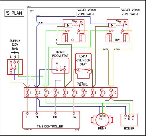
If you study the wiring diagram, the main pump is also run from terminal 10 - so whenever it's live (from whatever source) then it will be running.
The UFH control box has its own 230V supply (of a fused spur shared with the CH) so looking at the diagram, the neutral for the pump and boiler are not switched, if the boiler gets a live feed from the UFH, it will fire along with the pump.
Correct
the main concerns are what will happen if the UFH provides a live feed AND the DW or CH do as well at the same time.
Also, because the DW and CH zone values are connected to terminal 10, then the UFH is on, these will also be live. Will this turn them to open when they are not needed?
There is no feedback
from terminal 10 to operate any of the zone valves.
Each valve has a motor which is controlled by the circuit feeding it (programmer + tank stat for HW, programmer + room stat for CH). When powered, the motor winds the valve open, and when it's at least partially open, a microswitch (which is electrically separate from the motor) closes and links the orange and grey wires.
So you connect the orange and grey wires across <whatever> it is you want to control.
"Traditionally", this has been between a permanent live (terminal 1) and a single input on the boiler.
However, on some boilers there is a switched live output - ie it has two terminals, one of which is live when the boiler is switched on at it's main switch, and another that makes it fire. For these, it's best to remove the grey wires from terminal 1, and connect them to this switched output from the boiler - that way, you don't feed a live into the boiler when it's main switch is off. The pump may be connected as shown (between terminal 10 and neutral), or it may be controlled by the boiler.
It won't apply to your setup, but some modern boilers expect "volt free" switching - ie whatever connects to it's control terminals must not be connected to external supplies. Thus you'd move the grey wires to a spare terminal (eg 9), and connect these across the two control terminals of the boiler. The pump would be controlled by the boiler in this case. For the UFH, you'd use the "dry contacts" (the pair of terminals labelled as volt free on the UFH controller diagram) rather than feed mains into the boiler controls.
Personally, I'd use the volt free contacts on the UFH controller anyway, and wire then across the same terminals as the grey and orange wires from the HW & CH zone valves. It just "seems more logical" to me, rather than feeding it another live feed. Functionally it's the same though for your setup.