Hi,
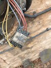
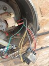
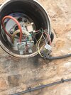
I need to rewire this relay as it seems to be dropping out during service. Its a Rockwell 240v relay. How do I work out what each terminal does?
Its in the flue of a Stanley Range Cooker. Connected to cooker, exhaust fan and a pressure switch.
I need to rewire this relay as it seems to be dropping out during service. Its a Rockwell 240v relay. How do I work out what each terminal does?
Its in the flue of a Stanley Range Cooker. Connected to cooker, exhaust fan and a pressure switch.