MPB - regs or common sense?

The idea with future regulations was that you needed a certain knowledge before being able to interpret the good book.

That knowledge being essential since the good book no matter how good cannot cover every situation and the guidance it provides is based on a series of compromises between several conflicting requirements.
 
Sponsored Links
I wasn't aware of that (I'm not very familiar with anything prior to "16th"), but it doesn't really surprise me. There seems to have been a tendency in many fields for regulations etc. to move in that direction over the past couple of decades - often in the name of 'flexibility' (which I think is one characteristic which regulations should, in general, not have!).

For comparison, here's an extract of a few regulations from the 14th edition related to the subject at hand:

D.10 The consumer's earthing terminal required by Regulation D.2 shall be bonded to the metalwork of any gas or water services on the consumer's premises in accordance with Regulations D.11-13.

D.11 Before the consumer's earthing terminal is bonded to the metalwork of any gas or water service, connection of the earthing terminal to an effective means of earthing complying with Regulations D.34 or D.24-26 shall be completed.

D.12 The bonding connections to any gas or water services shall be made as near as practicable to the point of entry of those services into the premises; provided that where there is an insulating section or insert at that point, the connection shall be made to the metalwork on the consumer's side of that section or insert.

D.13 Copper conductors for the bonding connections required by Regulation D.10 shall be of the appropriate size stated in Columns 5 and 6 of Table D.3; copper strip shall be of the appropriate cross-sectional area stated in Column 5 of Table D.3. Other metal bonding conductors shall be of equivalent conductance to that of the prescribed copper conductors. Connections to pipes of other services shall be made with clamps complying with B.S.951 and precautions shall be taken to avoid damage to the pipes.

NOTE 1. - In case of doubt regarding the method of connection to metalwork of another service (e.g. as to the presence or otherwise of the insulating section or insert referred to in Regulation D.12), the authority responsible for the service concerned should be consulted.

NOTE 2. - There are special requirements for bonding of metalwork to other services in P.M.E. installations (see Regulation D.34(iii) and Item 4(2) of Appendix 5).

NOTE 3. - For requirements for bonding or segregation of metalwork other than at the point of entry of services, see Regulation B.53.

D.14 The exposed metalwork of all apparatus which is required by these Regulations to be earthed, which might otherwise come into fortuitous contact with extraneous fixed metalwork shall be either effectually segregated therefrom or effectually bonded thereto so as to prevent appreciable voltage differences at such possible points of contact (see also Regulation B.53).

NOTE 1. - The extraneous fixed metalwork required to be bonded and earthed in these circumstances includes the following:

(i) Baths and exposed metal pipes, radiators, sinks and tanks, in the absence of metal-to-metal joints of negligible electrical resistance.

(ii) Where practicable, accessible structural steelwork.

(iii) Framework of mobile equipment on which electrical apparatus is mounted, such as cranes and lifts.

NOTE 2. - There are special requirements for bonding to metalwork of other services in P.M.E. installations (see Regulation D.34(iii) and Item 4(2) of Appendix 5).
 
NOTE 1. - The extraneous fixed metalwork required to be bonded and earthed in these circumstances includes the following:

(i) Baths and exposed metal pipes, radiators, sinks and tanks, in the absence of metal-to-metal joints of negligible electrical resistance.

I seem to recall a thread where a person was getting shocks from pipes while staning in the bath in an isntallation that ( apparently ) complied with the 16th.

If it had complied with the 14th then the pipes and bath would have been bonded together and therefor at the same potential.

provided that where there is an insulating section or insert at that point, the connection shall be made to the metalwork on the consumer's side of that section or insert.

Is this insulatiing section a left over from when the internal CPC had to be insulated from true ground in order that voltage operated earth leakage breakers would not be compromised by having their operating coil bypassed ?

The differential current RCD doesn't care how the earthing and / or grounding is achieved or happens to be connected so it is much better protection for the installation.
 
This came from a conversation I had with a certain Mr Cook of the IEE a good few years ago.

BTW wasn't it the same man who wrote a paper on the very topic of all things green & yellow?

I know who'll have a link.... BAN!!! BAN!!!
I'm thinking of Mr Cockburn.... :evil:
 
Sponsored Links
If one accepts that it is incredibly unlikely that supply pipes would introduce a non-earth potential, the MPB is merely joining two 'earths' together.
No it is not joining two earths together, It is joining an "earth" wire in the building to pipes outside the building that might be in contact with true ground.
OK, I was not totally explicit in my wording, for which I apologise, but this is really just playing with words. I was, of course, talking specifically about TT systems, and I perhape should have included the word 'effectively'. In other words, what I was saying was that, in such a system, if one accepts that it is incredibly unlikely that the supply pipes (or the TT earth electrode) would introduce a non-earth potential, then the MPB in such a system is effectively joining together two points which are both usually at/close to earth potential.

The confusion arises because the word "earth" is used for what is no longer an "earth". The "earth" wire in a modern install is a protective circuit CPC and is derived in many cases from the incoming neutral. Hence it may not be at ground potential. Only in a modern TT install is the CPC true ground where it is connected to a rod driven into the ground.
Indeed, but I would again remind you that my comments you are discussing were specifically about TT. As I've said previously, I have no problem with the concept of MPB in relation to systems other than TT, in which a fault external to the installation could result in the DNO's earth terminal having a potential very different from earth (hence different from the probable potential of supply pipes, hence potentially {excuse pun!} dangerous).
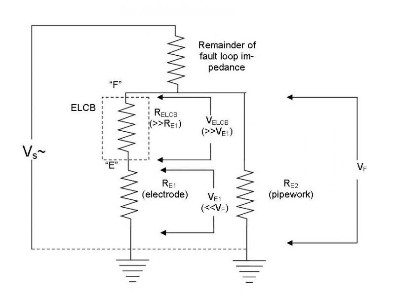
More confusion comes from the older TT installs where the CPC had to be isolated from ground if the voltage operated "earth" leakage breaker was to be effective as a safety device. It measured voltage between the CPC and the ground rod and if this became too high the trip operated.
Indeed, that's the very situation I inherited when I came to this property nearly 30 years ago, but I had that changed (to RCDs) immediately.

Even if there is an argument for having it (the only one I can think of being that vanishingly small probability that a supply pipe might introduce a non-earth potential),
It is the other way round. The supply pipe may introduce the true ground potential into a installation whose CPC ( "earth" wire " was not at ground potential
OK, maybe we are getting a little closer to a rationale for an MPB in a TT installation. As I keep saying, I really don't think one needs to consider the incredibly unlikely possibility that the earth electrode will itself introduce a non-earth potential (in the way that the DNO's earth terminal may, in systems other than TT - as you discuss below). However, that leaves us having to consider faults within the installation.

Given the non-zero impedance path to earth from the earth electrode (hence MET), a fault in the installation which gives rise to a current in the CPC will obviously cause the potential of the earth electrode (hence MET) to rise above true earth - in which case this would indeed, mean that the potential of MET and supply pipes (probably earth potential) would probably be different in the absence of (explicit or implicit) bonding. Maybe this is the thinking behind the concept of MPB in a TT installation? If so, one could debate how essential that really is, given that the regulations effectively require the presence of protective devices which limit how high the potential of the earth electrode/MET can rise (as the result of something happening within the installation - be it a fault or a human bondy in the current path) to a level deemed to be safe (~50V for a limited time). Maybe it's just belt-and-braces.
I still cannot think of a logical basis for trying to decide what cable size to use (e.g. for deciding that it should be at least half the size of the earthing conductor).
Where the CPC is derived from the neutral and the supply pipe is metallic and in good contact with ground then in the event of a network fault the current in the bonding cables could be very high as it forms an un-intentional but effectively part of the alternative route for current in the network neutral to return to the sub station.
You again seem to be missing the point that the comments of mine you are discussing were specifically about TT systems. I have discussed the very point you make, agreeing that this is a good reason for having robust MPB with a system other than TT. It's with TT that I have a bit of a problem. I also wrote (in my most recent post) that the fact that the resultant fault current in a bonded system would necessarily flow through both the earthing conductor and the MPB - which is not necessarily a logical basis for saying that one can be half the size of the other.

Kind Regards, John
 
provided that where there is an insulating section or insert at that point, the connection shall be made to the metalwork on the consumer's side of that section or insert.

This still exists in 17th, and I have wondered about it. If the supply pipes consist of 'an insulating section or insert' where they enter the property, I'm not sure that they actually represent extraneous conductive parts, do they? If not, they would not appear to require MPB, so that any bonding one chose to add would, in fact, effectively be Supplementary bonding.

This leads, tangentially, to another interesting aspect of my installation. Presumably because the person who installed the water meter did not want to get invoved with a 2" iron pipe which is probably 100 years old (he merely attached a reducer to 22mm copper to the end of this pipe), there is about 3 metres of water supply pipe within my property before the meter - and, in due deferrence to the regs, my MPB is attached on my side of the meter. I'm not sure if the there is continuity through the meter (the casing is certainly all plastic) but, if not, contunuity from my MPB to the true 'extraneous conductive part' exists only by virtue of the 4mm² strap which the water company put across their meter.

Kind Regards, John
 
exists only by virtue of the 4mm² strap which the water company put across their meter.

When we laid in our water service pipe ( self build 1980 ) there was talk about earth currents across stop cocks ( no meter in those days ) if our supply pipe was going to be metallic all the way to the house, ( its plastic ).

The confusion with TT and earth leakage breakers was also talked about.

Most houses around here were TT with voltage operated breakers and several had lead water supply pipes. In those houses with lead water pipes bonding the CPC to the water pipe effectively prevented the breaker from ever working. I recall that one house had a length of plastic pipe installed when central heating was installed as connecting the CPC to the boiler electrics meant it was then connected to ground via the water supply pipe. That was a far lower impedance to ground ( at least 20 yards of lead pipe in damp clay ) than the earth rod for the ELCB as the rod was a few feet of rod in an area that was well drained. So fault current went via the pipe to ground and bypassed the coil of the ELCB.
 
Most houses around here were TT with voltage operated breakers and several had lead water supply pipes. In those houses with lead water pipes bonding the CPC to the water pipe effectively prevented the breaker from ever working. I recall that one house had a length of plastic pipe installed when central heating was installed as connecting the CPC to the boiler electrics meant it was then connected to ground via the water supply pipe. That was a far lower impedance to ground ( at least 20 yards of lead pipe in damp clay ) than the earth rod for the ELCB as the rod was a few feet of rod in an area that was well drained. So fault current went via the pipe to ground and bypassed the coil of the ELCB.
Interesting, and I'd never really thought about that - I guess because I have never had any dealings with voltage-operated breakers other than to have them replaced with RCDs! If I recall correctly, there was no explicit bonding, as such, of any sort when I acquired this place with its volltage-operated breakers, and no water meter - so there was definitely a metal path to earth via the water supply pipes. However, there was inevitably some implicit bonding - e.g. via CPCs of supplies to immersion heaters, boiler etc. ... which, in view of what you've now made me think, makes me wonder if those voltage-operated breakers would actually ever have operated! (I think I still have them somewhere in my cellar - maybe a museum would like them!!)

As a matter of interest, can you remember what regulations said about bonding in the days when voltage-operated breakers were common? One might even have expected bonding to be 'banned' in that situation, even though that would have been a pretty futile gesture, given the near-inevitability of implicit bonding.

KInd Regards, John.
 
That knowledge being essential since the good book no matter how good cannot cover every situation and the guidance it provides is based on a series of compromises between several conflicting requirements.
You are obviously right that no set of rules, regulations, guidances etc. (or even laws), no matter how 'good', can be totally exhaustive in the real world. Indeed, attempts to be exhaustive and didactic can easily lead to unworkably complex documents and often a fair bit of 'silliness'.

However, good regulations/guidances etc. do (or should do) all they can to dictate the principles that should be applied when dealing with situations not explicitly covered by the regs (or whatever) - and I personally feel that BS7671 is sometimes lacking in that regard.

Kind Regards, John.
 
There is no problem with a voltage-operated ELCB in having metallic pipework or other material bonded to the installation (and hence to the ELCB's "F" terminal) and in contact with the earth itself, so long as the reference electrode (connected to the "E" terminal) is located so that its resistance gradient area doesn't overlap with the gradients of any of the other "unintentional" earth electrodes. For similar reasons, it's necessary that the conductor connecting the ELCB to the reference electrode is insulated so that stray parallel paths which would shunt the coil can't be formed (e.g. by running a bare conductor across structural steel in earth contact).

So long as there is no overlapping of the resistance gradients, the earth electrode will still provide a true earth reference and the ELCB will trip when the voltage on the "F" side (installation & bonded pipework) exceeds a certain level.

It's also important that the resistance gradient area of the earth electrode doesn't overlap with similar gradients from neighboring installations, otherwise a fault on that other installation which raises the potential on its earth rod will also raise the potential on the "E" terminal of the ELCB. If there is bonded pipework or other metalwork on the "F" terminal, that will then provide the true earth reference, resulting in the ELCB tripping due to faults on a different installation.

Dinner is nearly ready, but I'll find the relevant regulations and quote them later if you're interested.
 
I must be missing something here ....
So long as there is no overlapping of the resistance gradients, the earth electrode will still provide a true earth reference .....
I'm with you, and agree, so far ....
... and the ELCB will trip when the voltage on the "F" side (installation & bonded pipework) exceeds a certain level.
... but now I get slightly lost. If the "F" side is robustly bonded to the pipework and if (as is likely, particularly in the largely pre-plastic pipe days when voltage-operated breakers were common) that pipework is ('unintentionally') also at (or trying to be at) true earth potential, then it would seem to me that there would be no (or, at least, not enough) potential difference between "E" and "F" to trip the ELCB. If there were a substantial fault current to earth, that would obviously raise the potential of both the intentional earth (electrode) and the unintentional earth (pipework), but they would both move in the same direction and, if both intentional and unintentional earth impedenecs were equal, or near equal, there ought to be no appreciable pd between them, even under major fault conditions.

Can you help me understand what it is that I'm missing? Thanks.

Kind Regards, John
 
deadhorse4xq.gif
 
Hmmm! I asked for help with understanding what had been written, since I'm clearly missing something, but I really don't find that response particularly helpful to my understanding :LOL:. None of us understand everything without help. For those who already understand the explanation, the question I am 'flogging' may well feel like a dead horse - but for me there is a genuine problem of understanding that I would like to be helped to overcome.

John
 
If there were a substantial fault current to earth, that would obviously raise the potential of both the intentional earth (electrode) and the unintentional earth (pipework), but they would both move in the same direction and, if both intentional and unintentional earth impedenecs were equal, or near equal, there ought to be no appreciable pd between them, even under major fault conditions.

Can you help me understand what it is that I'm missing?

What you're not taking into account is the resistance of the trip coil in the ELCB, which is high in relation to the electrode resistance. Obviously any amount of current flowing through the resistance of the electrode to earth will raise the potential at the electrode by a certain amount, but in this case that current is limited by the relatively high resistance of the coil, so the voltage rise, even on a dead short L-E in the installation, will be small, unlike the voltage rise on the "pipework earth" on the "F" side of the ELCB, which is limited only by the loop impedance via that pipework electrode.

With an ELCB, the old Wiring Regs. specified a minimum size conductor between the ELCB and reference electrode of only 7/.029 (or 2.5 sq. mm. after conversion to metric), because the only current it would ever carry is limited to a very small value by the resistance of the ELCB's coil.
 
What you're not taking into account is the resistance of the trip coil in the ELCB, which is high in relation to the electrode resistance. Obviously any amount of current flowing through the resistance of the electrode to earth will raise the potential at the electrode by a certain amount, but in this case that current is limited by the relatively high resistance of the coil, so the voltage rise, even on a dead short L-E in the installation, will be small, unlike the voltage rise on the "pipework earth" on the "F" side of the ELCB, which is limited only by the loop impedance via that pipework electrode.
OK, in terms of what I wrote, I deserved that :) I confused matters totally by talking in terms of the potential of the earth electrode and the potential of the pipework. In terms of functioning of the ELCB, those potentials are irrelevant, per se; what matters is the pd across the ELCB coil (i.e. between its 'E' and 'F' terminals). However, despite introducing that confusion, my 'belief' (probably mistaken!) that the 'unintentional earth' will undermine functioning of the ELCB remains. Furthermore, I certainly didn't overlook the fact that the resistance of the ELCB's coil is high in relation to the earth path resistance - since that is central and crucial to my argument (since it results in most of the fault current going through the pipwork, rather than through ELCB to earth electrode). To understand 'how I see it', please consider the following rapidly created diagram, which hopefully is fairly self explanatory.


Initially, consider the situation with no bonded pipework - i.e. RE2 does not exist. For illustration, assume that RE1 is 10 Ω, RELCB is 200 Ω and that there is a fault which just results in the threshold value of VELCB for tripping (say 50V) to arise. It therefore follows that the current through the ELCB and earth electrode is 250 mA and that the 'remainder of the fault loop impedence' (forgot to give it a symbol on the diagram!), assuming a supply L-E of 230V is 710 Ω . Now consider that same fault but with bonded pipework (hence RE2) present, and with RE2 = RE1 = 10 Ω (quite plausible). RELCB, RE1 and RE2 together are equivalent to a single resistance of about 9.55 Ω, hence total loop resistance is about 719.55 Ω and total fault current about 320 mA. Of that total, about 305 mA will go through RE2 (i.e. through pipework to earth), and only about 15 mA will go through the ELCB to the earth electrode. The voltage across the ELCB coil (between terminals 'E' and 'F') will therefore only be about 3 V, far far too little to trigger the ELCB (assumed to have a 50V threshold).

If it is true that bonding to pipework which provides a low resistance/impedance (I really don't think there's much reactance involved, except in the ELCB coil, so the two will be very similar!) will not have a seriously deleterious effect on the functioning of an ELCB, there must still be something major that I'm missing.

Kind Regards, John
 

DIYnot Local

Staff member

If you need to find a tradesperson to get your job done, please try our local search below, or if you are doing it yourself you can find suppliers local to you.

Select the supplier or trade you require, enter your location to begin your search.


Are you a trade or supplier? You can create your listing free at DIYnot Local

 
Sponsored Links
Back
Top