No power getting to a Baxi boiler

Sponsored Links
I think you may have described the connections inaccurately.

Ignoring the CPCs (earths) you have only two wires from the switch to the timer but four from the timer to the switch.

The other wires into the timer from the switch, come from the connection blocks...

There are 5 in total: the 2 you high-lighted, plus 3 more which are just linked inside the switch patress, to the airing cupboard... (as per the photo)
 
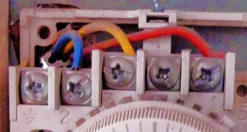
I don't see a Y/G at the stat - all I see are red, yellow and blue insulated conductors, and a bare CPC which disappears to somewhere, but is not connected to the stat's earth terminal. Are we both looking at thge same picture?

Kind Regards, John

John is right...
I can't believe I'm writing this (!) - but what seems to happen, is that the yellow in the room stat goes to the power supply switch - but isn't connected to anything there...
However, the bare wire that isn't connected in the room stat, goes to the power supply switch and is connected to earth !
I realise this is ridiculous - but it is how it was connected (and I've simply replicated that !!)
 
Sponsored Links
The other wires into the timer from the switch, come from the connection blocks...

There are 5 in total: the 2 you high-lighted, plus 3 more which are just linked inside the switch patress, to the airing cupboard... (as per the photo)
Ah, I see. Apologies.
 
So…
Thinking about it (and I hadn’t previously – I was just trying to act like a parrot !), there seems to be no reason why the cable to the airing cupboard goes into the power supply switch pattress. All that happens, is that it is connected directly to wires coming out of the timer.
I guess it is like that due to a lack of space – but it does cause some confusion !

If the cable went straight from the airing cupboard into the timer, the connections in the timer would be as follows:

1. Earth - Single yellow wire (power supply switch)
2. Neutral - Brown (power supply switch)
3. Live - Blue (power supply switch) and blue (boiler)
4. HW Off - Nothing
5. CH Off - Nothing
6. HW On - Red (airing cupboard) and brown (boiler)
7. CH On - Yellow (airing cupboard)

Connection block linking blue (airing cupboard) and yellow/green (boiler)

Does this make any more sense ? (I’m not totally convinced myself !)
What exactly will the cable going into the airing cupboard connect to ? (will it be the boiler stat ?)
 
There is more than one way that the wiring could be configured so it isn't really possible to say without seeing everything.

However, as said, obviously the live and neutral from the switch should go to L & N respectively at the timer.

Also from the timer
CH on should go via the room thermostat to operate the CH valve and
HW on should go via the tank thermostat to operate the HW valve.

A separate Live feed at the valves is switched on by the valve's operation to energise the boiler and the pump, either directly or through another switch in the boiler in which case a separate live is required at the boiler..
So the boiler and pump are only switched on when one of the valves opens.

All neutrals should be connected together and
all CPCs (earths) should be connected together.

Ideally a cable from each item goes to a central wiring box where they can be connected as required.
 
OK.
So what I can see, is that the room stat connects to the power supply switch: the power supply switch connects to the timer and either the a central wiring box – or the tank thermostat; the timer connects to the boiler…

I’m pretty sure that the boiler connects to nothing other than the timer (via the 3 core cable). I’m also pretty sure that the room stat only goes into the power supply.
The timer also goes into the power supply – but then on to the airing cupboard (and the central wiring box or the tank thermostat).

The problem I have is that I understand what you are saying – and it makes sense – but it contradicts what I am seeing.
I can believe that I’ve got something wrong – but not as much as your solution would suggest !

Are there any steps I can take to clarify things further – or anything I can try which won’t have severe consequences if it goes wrong (I don’t want to blow up the PCB for example !!)
 
I am in the same boat as you.
What I see doesn't make sense but you say it worked.

I started to write an explanation of what you seem to have but there are so many things that would go wrong if that were the case there was no point.

For example the CHON going straight to the boiler would switch it on when the programmer called but it would be unlimited by the thermostat (the yellow wire should do this but you say it is not connected to anything) and if the valve did not open then the water would not circulate.

Really I don't know what else to say.

If you understand the diagram then start again.
If not then I think you will have to get an electrician.
 

DIYnot Local

Staff member

If you need to find a tradesperson to get your job done, please try our local search below, or if you are doing it yourself you can find suppliers local to you.

Select the supplier or trade you require, enter your location to begin your search.


Are you a trade or supplier? You can create your listing free at DIYnot Local

 
Sponsored Links
Back
Top