LOL !
I'll do my best...
I'll do my best...

Hang on.
") )
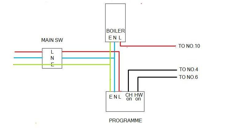
)GoodWhat is more frustrating, is that after hours of staring at EFLs ‘S’ plan wiring diagram and comparing it to my own set-up, I honestly think I could get my system working…
Good. Make absolutely certain.My wiring box seems to mirror the wiring diagram exactly (maybe not surprisingly), so I really only have to work out how to connect the timer and boiler…
They may have used the earth wire as a live.Currently, junction 10 in the wiring centre is going to the earth in the boiler. My plan would be to change that to the boiler live…
To enable that to happen, I would connect the boiler earth, to the earth in the timer and disconnect the boiler live from HW ON in the timer…
Yes change them round.That would be the extent of the changes I would make (though I might also change round live and neutral in the timer, as they contradict the labelling on the timer).
Yes, see below.It doesn’t sound a lot – but obviously, moving to live, something that is currently going to earth, is quite a big thing to do !
The S plan only uses a switch live. Switched by either of the valves.The only concern in my mind, is caused by the fact that my boiler uses a switched live and not a permanent live – and whether the ‘S’ plan wiring diagram is OK with that…
So what should I do ? Make the changes I have suggested – or keep trying to find an electrician (almost regardless of who I can get !)…?
Remove the Brown from the Timer CHon and find the other end of it.
It should not be in CHon so you may be able to use it and put the earth wire in its proper place. See if it goes to the boiler Live. It may be that earth which is connected to the Blue at the switch.
Can you tell from the colour and style of the Brown from CHon which wire it is at the wiring box? Let me know.
At the wiring box - the two Oranges (10) connect to Blue.
This Blue should go to the live on the boiler - it may do.
However the Live from the pump should also connect to here.
Where does the pump Live go at the moment
If you need to find a tradesperson to get your job done, please try our local search below, or if you are doing it yourself you can find suppliers local to you.
Select the supplier or trade you require, enter your location to begin your search.
Are you a trade or supplier? You can create your listing free at DIYnot Local