I have an old Myson Apollo Fanfare 15/30 with what I'm sure is a Y plan system. Now, the programmer (which I replaced like for like a few years ago) is playing up again so I would like to replace it with something with more flexibility such as the Honeywell ST9400C.
I assume this is an easy enough job... Once you know what to connect to what!
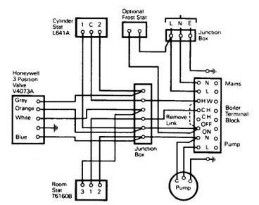
As the existing programmer is an integral part of the boiler, as far as I know there is no 'back plate' so am I right in thinking all I would need to do is cut the wires off at the multiplug (see image) and connect to the new programmer?

I assume this is an easy enough job... Once you know what to connect to what!
As the existing programmer is an integral part of the boiler, as far as I know there is no 'back plate' so am I right in thinking all I would need to do is cut the wires off at the multiplug (see image) and connect to the new programmer?