Pump/boiler running continuously...

I will wire it all in as the remaha diagram tonight (involves some drilling through the walls to run the extra wires and get the permanent feed, which I think is why the fitter couldn't be bothered...)

Thing is though I don't see why that helps fix the fact that the switched live is not switching UNLESS the current setup is causing the components to fail - (boiler is firing up and running happily at the mo, as is the pump - though I agree the boiler controlling pump overrun is a good thing)

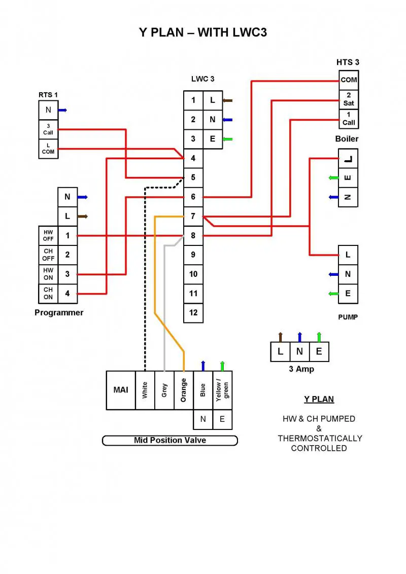
I'm trying to get the pdf of my wiring diagram saved as a picture so I can share it.

Thanks again for your thoughts (don't want my 2nd comment about the switched live to sound ungrateful), and I do agree it's a good idea to wire it all in exactly as the manufacturer describes then we all know what's what.
 
Sponsored Links
I will wire it all in as the remaha diagram tonight (involves some drilling through the walls to run the extra wires and get the permanent feed, which I think is why the fitter couldn't be bothered...)
Having said you should always follow the mfrs wiring, I am going to suggest a minor change, in case it makes life easier for you! The diagram shows the boiler X6 and the wiring centre separately fed from the Switched spur. You could also feed the boiler X6 and earth from the wiring centre terminals 1, 2 and 3; i.e the spur only feeds the wiring centre. You can then use a four core cable between wiring centre and boiler (fourth core goes from 8 to X2/1).

The same goes for the pump. It could be connected to terminals 8 and 9 and those terminals connected to X4.

Make sure all polarities are correct. The manual says this is important.

I don't see why that helps fix the fact that the switched live is not switching UNLESS the current setup is causing the components to fail
That's why I want a wiring diagram ;)
 
Forgive me butting in again but I'm wondering if the boiler has more than one source of mains power and is actually supplying Live to the LWC3 connector 7 itself.
 
Sponsored Links
Can't be unfortunately - there are only 3 wires going to the boiler and they are wired as per the diagram.
 
Here's how I have wired in the system currently. Any thoughts?
Basically it is correctly wired, apart from the actual connections to the boiler and pump.

Connect pump directly to X4 (via spare terminals on the LWC3 if easier)
Connect boiler power (X6) directly to LWC3/1, 2 and 3.
Connect LWC3/7 to X2/1
Remove links in X2
 
Partial success...

The cylinder stat is working and the boiler is now wired in correctly as per the remaha diagram and hence running the pump as it should - which is much better as it can now run the over run. Also the CH side of things on the programmer seems to work fine.

However, the feed from the HW side of the programmer is always 240V no matter what it says it's doing and the room stat appears to be constantly live also, whenever it is powered.

Before I go and replace these items the last thing that is original is the mid position valve - could it be the cause of these things going belly up?

In the current situation the orange wire is constantly live and the valve isn't moving at all.

I have a new MPV but don't want to fit it unless needs be as it's a snap on one and the old one isn't.

Any ideas?
 
Partial success...

The cylinder stat is working and the boiler is now wired in correctly as per the remaha diagram and hence running the pump as it should - which is much better as it can now run the over run. Also the CH side of things on the programmer seems to work fine.
That's a step in the right direction!

However, the feed from the HW side of the programmer is always 240V no matter what it says it's doing and the room stat appears to be constantly live also, whenever it is powered.
They may be getting voltage back fed from somewhere else. But first the programmer and the room stat needs to be checked out.

The boiler will not run during some of these checks

Disconnect the wires from the CH ON, HW ON and HW OFF terminals of the programmer. Then check the voltages of these terminals when turned on and off.

CH On should read 0v when CH is turned OFF and 240v when turned on.
HW On should read 240V when HW is turned ON and 0V when turned off; HW Off should read 240V when HW is turned OFF and 0V when tuned on

Check with the various options , i.e when timed by the clock or continuous etc. The idea is to see if there is any option which gives incorrect results.

If the programmer checks out OK, reconnect the programmer wires.

Now we check the thermostats.

Disconnect the valve white, grey and orange wires.

Turn CH ON and room thermostat down. Connect meter to the terminal which held the white wire; the meter should read 0V. Turn the room stat up and it should read 240V. Turn CH OFF

Turn HW OFF and HW stats down
Measure voltage on grey wire terminal; it should be 240V
Measure voltage on orange wire terminal; it should be 0V
Turn HW stat up; voltage on grey terminal should be 240v and on orange terminal 0V
Turn HW stat down and HW ON; voltage on grey terminal should be 240v and on orange terminal 0V
Turn HW stat up; voltage on grey terminal should be 0V and on orange terminal 240v (The boiler will run and HW side of valve get hot)

If this checks out we are left with the valve

Power OFF
Connect white wire to a permanent live
Turn Power ON; valve will move to middle position and boiler run. Both CH and HW side of valve will get hot.
Power OFF
Connect Grey wire to permanent live
Power ON; Boiler should run and CH side of valve get hot
Turn HW stat down; boiler should stop
Turn HW OFF; boiler should stay off
Power OFF
Reconnect orange wire to correct terminal
Power ON; boiler should light and CH side valve get hot.

If this check out, the valve is OK
 
That is PROPER helpful!

I am pretty sure I have done exactly that test for the Programmer - pretty sure it's shot on the HW side (both HW ON and HW OFF are constantly live I think!). As for the room stat I will test that as prescribed as I am not sure I have done that without the MPV disconnected.

I now feel confident I have good clarity on the direction ahead. Here's hoping I might have me some proper heating soon and can get back to fitting me kitchen for chrimbo!

Thanks for your help. Will report back on monday.
 
I now have a similar issue , the boiler is a Broag Avanta 24S and X6 block is fed from Wiring Centre { port 8 }.
I knew it was wrong but when I set it up as per the handbook { removed links X2:1 to 4 and X2:3 to 4 then set permenant L/N/Earth to X6:1,2and3 then plugged port 8 from wiring centre to X2:1 as per standard y-plan } the boiler comes up , fires once then sits at 0 on the panel waiting to be called , however , when wiring centre pin 8 comes up to 230V it does nothing .
230V comes and goes with thermostats as expected , so I reckon I'm missing something on the boiler , any ideas ?????

Current/original boiler block setup :

X2 : pin 1 linked to pin 4
X2 : pin 3 linked to pin 4
X2 has no other connections

No blocks for X3 , X5 or X7 connectors

X6 : Temp Live from Wiring Centre 8
X6 : Permenant Neutral

X9: pin 5 linked to pin 6
X9 : pin 7 linked to pin 8
X9 has no other connections
 

DIYnot Local

Staff member

If you need to find a tradesperson to get your job done, please try our local search below, or if you are doing it yourself you can find suppliers local to you.

Select the supplier or trade you require, enter your location to begin your search.


Are you a trade or supplier? You can create your listing free at DIYnot Local

 
Sponsored Links
Back
Top