RCD blowing cutout fuse

...looking at the circuit diagrams it would seem that the test button circuit is on the load side of the RCCB so would only be energised until the breaker trips. ...
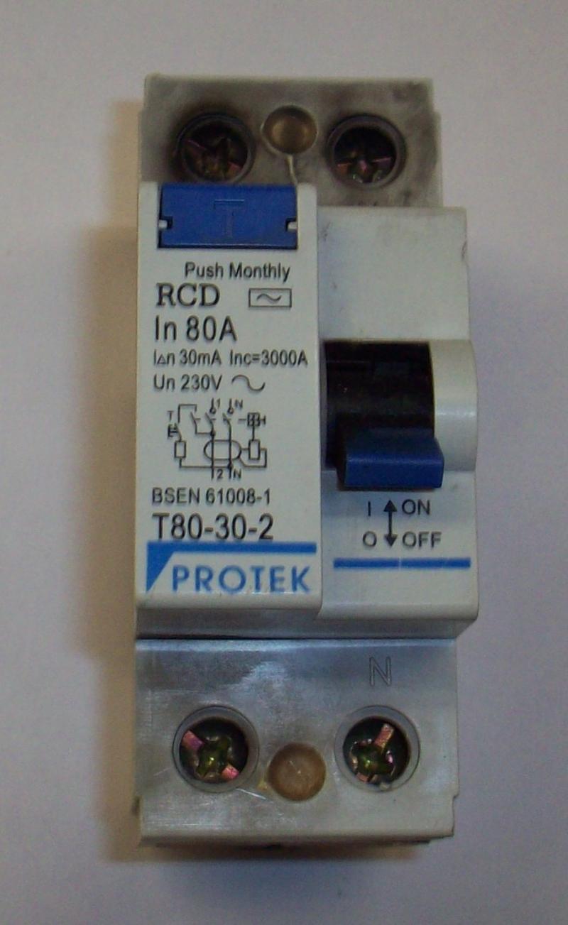
As I said, that's certainly what I would have expected.
Assuming it tripped in the proper time this, presumably, would not cause overheating but if the device were faulty how long did it really take?
She appears to be reporting that the bang happened the moment she touched the button - but that could obvioulsy mean anything from a few mS to a few hundred.
Also, I have read many threads about the wiring of RCDs and I think it is accepted that wiring the other way round, i.e. supply to the bottom does not matter but this would then mean the test button circuit would be on the supply side causing the current to flow until the button was released. Either way, if that were the cause, it does seem to be less than satisfactory.
As you say, very much less than satisfactory I would say. I'm sure one wouldn't have to keep one's finger on the button for long to fry the resistor.

Kind Regards, John
 
Sponsored Links
The test resistor is usually only in the circuit for <40mS, the Wylex one I have on the shelf has a 1.8K resistor in it hence around 130mA will flow at 240v.!
Shoudn't the test current through the resistor be closer to 30 mA to test the device trips at its rated trip current, hence a resistor value of 8 k ohms 8k2 being the nearest standard value.

You'd have thought so, but sticking my fluke across the RCD with the test button closed read around 1800 ohms.
Maybe they just want to make sure it trips when pressed, it is only really there to check the mechanism.
 
Have had 1 or 2 rcd sockets blow up on me but not sure whether it was when i tried to reset the things rather than actually testing them.
In your daughters case is it possible she was ressetting her rcd switch under a substancial load or is she in the habit of isolating the load first.
 
You'd have thought so, but sticking my fluke across the RCD with the test button closed read around 1800 ohms.
Maybe they just want to make sure it trips when pressed, it is only really there to check the mechanism.
We've discussed this before. One suggestion has been that the test current may be designed to be at least 60mA, because there theroretically (although very unlikley- one has to postulate pretty bizarre scenarios) could be a current imbalance of nearly 30mA 'in the other direction' before the test current was applied - in which case it would take nearly 60mA through the resistor to cause a trip. However, even that doesn't justify 130mA - as you say, it may be intended just as a brute-force 'qualitative' test of the mechanism.

Kind Regards, John
 
In your daughters case is it possible she was ressetting her rcd switch under a substancial load or is she in the habit of isolating the load first.
She wasn't trying to re-set it - merely test it - and, as far as I am aware, there was no significant load at the time she pressed the test button.

Kind Regards, John
 
I apreciate that john :)
But normally after testing one would then reset.
When big bangs are involved its sometimes easy to forget what stage they were at

Though as she was educated by you, each stage was no doubt logged, verified and filed :LOL:
 
I apreciate that john :)
But normally after testing one would then reset. When big bangs are involved its sometimes easy to forget what stage they were at
I think she had the sense (or fear!) to realise that after touching the test button caused a big bang and the meter to go dead, there was no point in attempting to re-set - or, to put it more in the language she used "she was not going to touch anything after that!".

Anyway, as I'll shortly be reporting (after an autopsy), all is now sorted.

Kind Regards, John
 
OK, all sorted. No damage seemed to have been to anything other than the RCD (not even cables connected to it). I managed to get an RCD to fit, and a very nice man from the DNO turned up in about 60 minutes from being summoned.

Autopsy has been undertaken, but I have to say that I so far have only an 'open verdict'. ...see all the piccies below.

Externally, there was blackening around the region of both L and N supply-side terminal screws (and slightly in the region of the load side L screw, but the treminsla themselves were pristine, as were the ends of the cables and the busbar lug.

Inside, everything was covered in lots of soot - it obviously was quite a significant 'bang'. Insulation on the supply-side incoming conductors (both L and N) is somewhat damaged. I couldn't really work out where the test switch mechanism was, or had been.

The electronics on the little PCB board (including a 1.8k resistor, which, per previous discussion, is probably the 'test reistor') were all perfectly intact, showing no signs of any thermal damage - they even escaped the soot which got nearly everything else.

I therefore don't know exactly what happened - maybe my early suggestion of some sort of 'internal collapse' of the mechanism, resulting in the main L & N conductors coming into contact, could be an answer. Any thoughts/ideas.?

Enjoy the pics....

Kind Regards, John
 
Haven't we had similar queries before, along the lines of "this switch went BANG" ?

Conjecture before has been some form of build up (conductive soot/whatever), then a bit of arcing as the switch/breaker operated was the last straw - followed by a flashover with the deposits of soot/carbon acting as the initial conductive path until a good ionised air channel has developed. Once the arc is going, then it's going to self sustain until "something blows" upstream.

So the fact that it's an RCD being tested is not relevant, it's a switch breaking a load.

If you clean up the parts, is it possible to determine where the arcing occurred ? For something to take out the service fuse, I'd expect there to be "significant" arcing damage visible.
 

DIYnot Local

Staff member

If you need to find a tradesperson to get your job done, please try our local search below, or if you are doing it yourself you can find suppliers local to you.

Select the supplier or trade you require, enter your location to begin your search.


Are you a trade or supplier? You can create your listing free at DIYnot Local

 
Sponsored Links
Back
Top