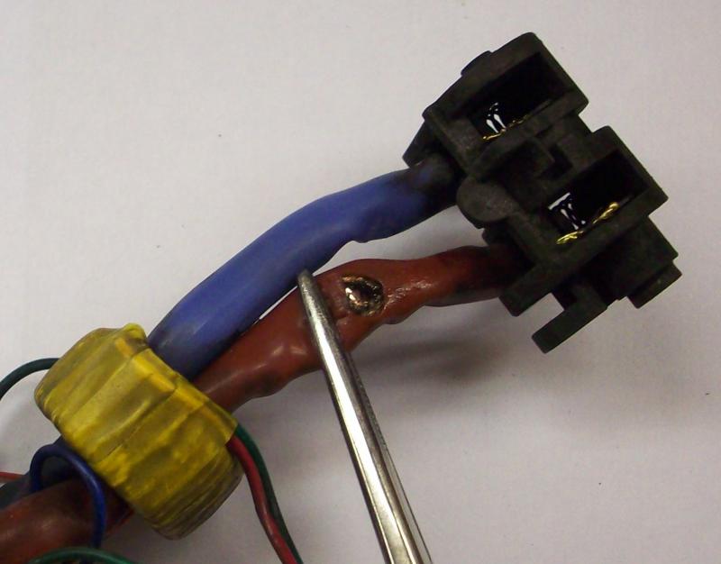
Though it's at least done one part of it's job - protect the person operating it from injury!
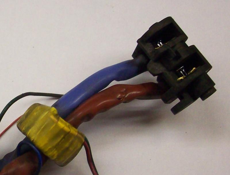
Yes looks like an internal L - N short, possibly small clearances between the two were part of the cause
Yes looks like an internal L - N short, possibly small clearances between the two were part of the cause