Vaillant Boiler wiring

Joined
4 Jan 2007
Messages
37
Reaction score
0
Location
Huntingdonshire
Country
United Kingdom
We are in the process of having a new boiler installed. Neighbours an RGI and is happy to do all of the corgi essential items leaving me to do the rest with help from him as needed.

We had previously replaced the old programmer and cylinder stat with new and included a room stat which the old system didn't have.

All of this worked ok with the old boiler, and I'm sure will be ok with the new boiler but before i connect it up i would like somebody who's familiar with Vaillant system boiler to confirm that what I'm planning to do is ok.

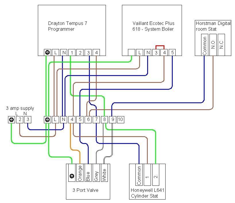
All of the components being used are shown on the wiring diagram below which i hope makes sense to everybody (Well those that understand wiring diagrams that is.. ;))

I read somewhere that the Red link across boiler terminals 3 and 4 should be removed and new supply cable only connected to terminal 4. But i've also read that the neutral supply for the 3 port valve should come from terminal 5. I'm not sure that this is correct as i would have thought that the 3 port valve N should be connected to the wiring block N terminal.

Could somebody confirm which is the correct way of wiring this up.

Thanks in advance for any help given


Boilerwiring.jpg
 
Sponsored Links
That diagram looks OK from a quick scan, you need to remove the link for the external controls. and terminal 5 is just an extra neutral; so don't panic.
 
Remove link (and keep for future testing) ignore terminal 5. All neutrals will be commoned at the wiring center.

If main 3 amp fused switch is in the airing cupboard you will need to fit a fan isolator at the boiler for servicing etc, so that both lives are killed when it is switched off.
 
Dan & Gas4you thanks for the replies

just to summarize I need to:-

1. Remove red link between boiler terminals 3 and 4

2. Remove Neutral wire between boiler terminal 5 and wiring center terminal 5

3. Add neutral wire from wiring center terminal 5 and wiring center N terminal.

Correct? :)

Oh yeah and ensure that total electrical isolation can be carried out at the boiler location. ;)
 
Sponsored Links
1) Yes

2) Yes

3) I would normally just wire the valve neutral straight back to the neutral block (2). 5 is normally the switched live return from the room thermostat.
 
Lovely diagram.

You may find that when wired in this configuration the boiler is always electrically on (but not calling for heat) even if you turn the boiler I/O switch off.

We always take the Programmer Clock perm Live feed from Pin 3 to avoid this (dangerous) scenario, which has always been the Vaillant recommended method in the past.

I'll have to check the ecoTEC manual to see if they have changed it in the last couple of years.
 
Simon, re our previous 'discussion' on this topic, it is no longer applicable to the ecotec plus range and indeed wasn't on the ecomax range.

It was on the older models, not sure about the turbomax range though.

I did check this with Vaillant and their engineer last time, gave me such a detailed tech answer down to pcb level that it went right above my head :rolleyes:
 
Agree with previous poster. Boiler could be switched off at the front panel but could still have live feed to it from the programmer.

To avoid confusion either allow boiler (3) live to feed timer or use timer that requires links so that terminal 3 is the source of live feed to HW and CH contacts in the programmer.
 
But thats the reason that a fan isolater should always be fitted on a boiler with switched live and permanent live connections, to make safe forservicing etc.
 
Thanks for the replies and the complements on the wiring diagram.
(I'm a structural engineering draughtsman so no big deal ;))

The boiler is in an upstairs cupboard. The 3 amp supply, wiring centre, timer and 3 port valve are all located in the airing cupboard across the landing.

So to make the circuits electrically safe for servicing I should either :-

1. Move the 3 amp supply from the airing cupbaord to a point next to the boiler with it marked boiler and feed the rest of the circuit back from there.

or

2. Install a fan isolator next to the boiler, fitted between the 3 amp supply and the wiring centre to completly isolate the circuit

or

3. Feed the timer from the boiler terminal 3.

I prefer the sound of either option 1 or 2 with 1 being my favourite.

Any thoughts welcome.
 
Dave

Simon, re our previous 'discussion' on this topic, it is no longer applicable to the ecotec plus range and indeed wasn't on the ecomax range.

It was on the older models, not sure about the turbomax range though.

I did check this with Vaillant and their engineer last time, gave me such a detailed tech answer down to pcb level that it went right above my head
__________________

This did not make sense to me with my knowledge of the Vaillant PCB. So I checked the manuals here and on the web. Both say Pin 3 should be used as the supply to controls.

I then checked with Vaillant tech today (Thursday) and they confirmed that a 6 series with external controls should be fed from pin 3.

I suggest the original poster reads the Vaillant manual , and thus complies with CORGI's stipulations. What the rest of us do is up to us, but with over 700 of ours out there I do know how to wire em.
 
Sorry Simon but totally disagree and with tech support. My mate does as well who is the Vaillant engineer.

The tech support was probably group service based!

As you pointed out months ago this was needed on the older boilers because of the overheat protection.

Any way not wanting to get into another disagreement so I'll just stick to what I know ;)
 
Well the Vaillant manual is absolutely clear, all controls to go between pin 3 and 4. Even Vaillant's own brand controls (240V) are wired this way.

Why do you think the roomstat and timers go across pin 3 and 4? Why do they not go across permanent live and pin 4? It's because it backfeeds the boiler when the on off switch is set to off.

We all advocate following MIs............. except in this instance it seems. You don't have that choice, if the MIs dictate it, the boiler has to be fitted that way. Saying you have a mate who is a Vaillant service technician does not let anyone off the hook.

Assuming he is allowed to rewrite the installation manual, then we can all do it his way. Until he is promoted due to his insight, we have to rely on those currently charged with that responsibility - the UK product line and the design team in Germany.
 
The new boards on ecotec and ecomax don't back feed, not sure about turbomax though.

Any way we'll just have to agree to differ. My mate has knowledge straight from Vaillant service dept and training. He's been with them since year dot, first as an employee and then as their agent and is one of the most respected engineers thay have left, I know this from conversations unassociated with him and unknown by him at director level.

What he doesn't know about Vaillants could be written on a postage stamp in block capitals.

Anyway we have both made our points, nuff said ;)
 
G4Y and SimonD sorry to have started another disagreement over how these boilers should be wired, i didn't mean to. honest :LOL:

Anyway getting back to the isolation issue. I'me getting the feeling that the best method to satisfy both points of view would be to:-

Move the 3 amp supply so that its next to the boiler and then wire the timer back from boiler terminal 3.........i think :confused:

Thanks again for all the help
 

DIYnot Local

Staff member

If you need to find a tradesperson to get your job done, please try our local search below, or if you are doing it yourself you can find suppliers local to you.

Select the supplier or trade you require, enter your location to begin your search.


Are you a trade or supplier? You can create your listing free at DIYnot Local

 
Sponsored Links
Back
Top