Hi
My parents recently moved into a static caravan that they are living in for 11 months of the year. They have a Morco FEB-24E boiler which they use for their heating and hot water. The boiler works brilliantly except it is very limited in its controls. It has a mechanical clock timer with jumpers for on/off with a manual override for either completely on or completely off. The caravan is either red hot or freezing. There is no room thermostat fitted and the outside temperature is currently -11C where they are!
I have previously fitted a wireless programmable to our boiler at home but I could look at the wiring for the clock and bought one from the boiler manufacturer. The Morco doesn't have one available from the manufacturer.
I am therefore after an easy to use wireless box of tricks that I can buy and fit myself (or simple instructions for my father).
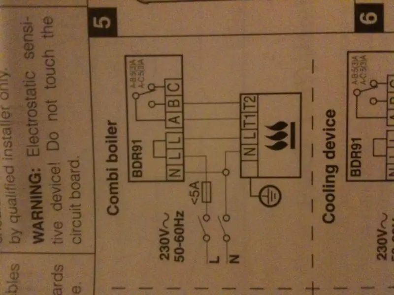
I have attached a link to the boiler which shows the wiring diagram. I'm sure this is a simple set up and hoping someone can quickly take a peak and advise the way to proceed.
The wiring is page 8!
http://www.morcoproducts.co.uk/resources/FEB24E_User_Manual_Web_Compressed.pdf
Thanks in anticipation.
Paul
My parents recently moved into a static caravan that they are living in for 11 months of the year. They have a Morco FEB-24E boiler which they use for their heating and hot water. The boiler works brilliantly except it is very limited in its controls. It has a mechanical clock timer with jumpers for on/off with a manual override for either completely on or completely off. The caravan is either red hot or freezing. There is no room thermostat fitted and the outside temperature is currently -11C where they are!
I have previously fitted a wireless programmable to our boiler at home but I could look at the wiring for the clock and bought one from the boiler manufacturer. The Morco doesn't have one available from the manufacturer.
I am therefore after an easy to use wireless box of tricks that I can buy and fit myself (or simple instructions for my father).
I have attached a link to the boiler which shows the wiring diagram. I'm sure this is a simple set up and hoping someone can quickly take a peak and advise the way to proceed.
The wiring is page 8!
http://www.morcoproducts.co.uk/resources/FEB24E_User_Manual_Web_Compressed.pdf
Thanks in anticipation.
Paul