Ethernet-controlled boiler

Joined
11 Jan 2011
Messages
380
Reaction score
22
Location
Oxford
Country
United Kingdom
Note: The thermostat connection on your boiler quite possibly runs at lethal voltages, although that's not always the case. You should consult a qualified electrician before attempting any projects like this. Unlike the prototype described here, you should at least put the thing into some kind of enclosure and arrange the high and low voltages to be in distinct areas. The three (or 2) core cable between your boiler and themostat needs to (AFAIK) follow all the requirements of any other house wiring (safe zones and other considerations). I'm posting this here in case the low-voltage side of things is of interest. Stay safe!

full


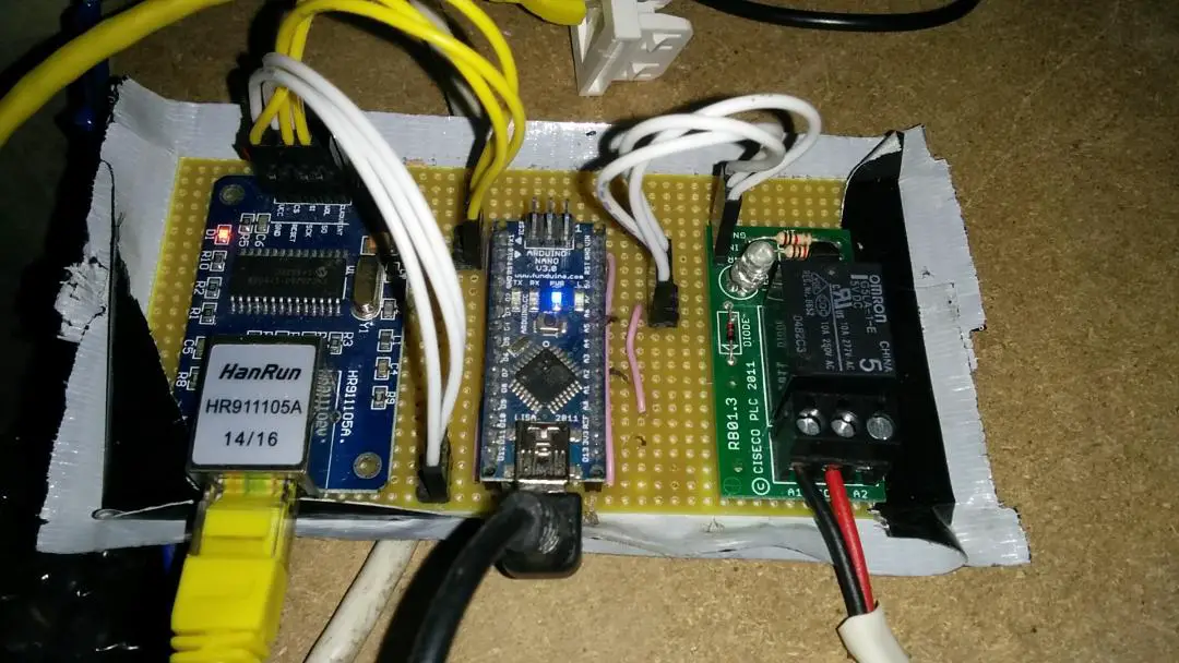
For my controller I used the following components:

Arduino Nano v3.0
Cost: £3.20

ENC28J60 Ethernet LAN module

Cost: £1.82

Omron 5v relay module or equivalent

Cost: £0.99

I already had an old mains -> USB -> mini-b adapter from some defunct equipment, but you can also get these from ebay.

In addition, you need either:
Some interconnecting Dupont jumper wires, like these.

== OR ==
Connect it together using solder, stripboard and board stand-offs/glue gun.

In the picture I've used Multicomp crimps, Various different housings, and a Multicomp ratchet. But for this project that's probably overkill.

I looked at the following guide for connecting the ENC28J60 module to an Arduino:
http://www.instructables.com/id/Add-Ethernet-to-any-Arduino-project-for-less-than-/
But that's for the Arduino Uno. If you want dirt-cheap you can save money (and space) with a Nano.

I used Arduino IDE version 1.8.2. The Ethercard library is used to talk to the ethernet module. For connecting the ENC28J60 to the Nano I just used the defaults expected by Ethercard (see the readme).

If you google for Arduino Nano pinouts one of the first hits is this diagram.
Each pin has umpteen names, but the numbers in purple are the ones the github page is talking about.

The relay module has only three connections, 5v, GND and control. The control goes to pin A2 (digital IO pin 16 in my source below).

To keep things simple I just connected the ethernet controller in series with a room thermostat, as I already had that, and it seemed pointless to rip it out and put in a temperature sensor, LCD display and program in hysteresis and so on (although it would surely be fun).

So my web interface is just a simple on/off switch:

full


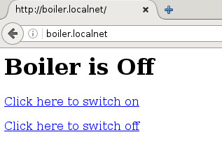
Yeah, I know, I'll improve on it later, early days and so on.

Finally here is the code:
Code:
#include <enc28j60.h>
#include <EtherCard.h>
#include <net.h>


// ethernet interface mac address, must be unique on the LAN
static byte mymac[] = { 0x00,0x81,0x1e,0x76,0x17,0x68 };
static byte myip[] = { 172,17,0,15 };
static byte relay_state = 0;  // initial state off
#define BOILER_PIN  16


static void BoilerOn()
{
  relay_state = 1;
  digitalWrite(BOILER_PIN, HIGH);
}

static void BoilerOff()
{
  relay_state = 0;
  digitalWrite(BOILER_PIN, LOW);
}


byte Ethernet::buffer[500];
BufferFiller bfill;

void setup () {
  Serial.begin(9600);
  if (ether.begin(sizeof Ethernet::buffer, mymac) == 0)
    Serial.println( "Failed to access Ethernet controller");

  if (!ether.dhcpSetup())
    Serial.println("DHCP failed");

  // set boiler pin to output
  pinMode(BOILER_PIN, OUTPUT);

}


static word homePage() {
  bfill = ether.tcpOffset();
  bfill.emit_p(PSTR(
    "HTTP/1.0 200 OK\r\n"
    "Content-Type: text/html\r\n"
    "Pragma: no-cache\r\n"
    "\r\n"
    "<h1>Boiler is $S</h1>"
    "<p><a href='/on'>Click here to switch on</a></p>"
    "<p><a href='/off'>Click here to switch off</a></p>"
    ), relay_state?"On":"Off");
  return bfill.position();
}


static word onPage() {
  BoilerOn();
  bfill = ether.tcpOffset();
  bfill.emit_p(PSTR(
    "HTTP/1.0 200 OK\r\n"
    "Content-Type: text/html\r\n"
    "Pragma: no-cache\r\n"
    "\r\n"
    "<h1>Boiler is now on</h1>"
    ) );
  return bfill.position();
}


static word offPage() {
  BoilerOff();
  bfill = ether.tcpOffset();
  bfill.emit_p(PSTR(
    "HTTP/1.0 200 OK\r\n"
    "Content-Type: text/html\r\n"
    "Pragma: no-cache\r\n"
    "\r\n"
    "<h1>Boiler is now off</h1>"
    ) );
  return bfill.position();
}


void loop () {

  word len = ether.packetReceive();
  word pos = ether.packetLoop(len);
 
  if (pos)  // check if valid tcp data is received
  {
    if(strncmp((char *)Ethernet::buffer + pos, "GET /on", 7) == 0)
    {
      ether.httpServerReply(onPage());
    }
    else if(strncmp((char *)Ethernet::buffer + pos, "GET /off", 8) == 0)
    {
      ether.httpServerReply(offPage());
    }
    else if(strncmp((char *)Ethernet::buffer + pos, "GET /", 5) == 0)
    {
      ether.httpServerReply(homePage()); // send web page data
    }
  }
}
 
Last edited:
Links in this post may contain affiliate links for which DIYnot may be compensated.
Sponsored Links
arrange the high and low voltages to be in distinct areas.
High voltage??? You have over 1000v on there?
 
He's referring to the pcb's he has, there is only 5v and the boiler thermostat/control which at most will have 230v on.
Where do you get 1kv from?
 
Sponsored Links
He's referring to the pcb's he has, there is only 5v and the boiler thermostat/control which at most will have 230v on.
Where do you get 1kv from?

https://en.wikipedia.org/wiki/High_voltage

"The numerical definition of 'high voltage' depends on context. Two factors considered in classifying a voltage as "high voltage" are the possibility of causing a spark in air, and the danger of electric shock by contact or proximity."

So if you look hard enough you will find a definition good enough to prove anyone wrong :rolleyes:. So what he's referring to is the 1000v (high voltage due to arcing risk). Technically correct, however the context here is of course 5v supply to the Nano.
 
Version 2

You can instead use a Nano ethernet shield to reduce the wiring, at ever so slightly higher cost.


Mine arrived a couple of weeks ago but I only just got around to trying it out. Surprisingly, the code worked without modification.

 
Links in this post may contain affiliate links for which DIYnot may be compensated.
After running with the Nano ethernet shield for a week, it seems it's more reliable than the v1 design. The main difference in this configuration is that the Nano shield has its own 3.3v regulator i.e. this little fella:

full


Stupidly I never checked the current available from the Nano 3.3v supply, which doesn't come from a proper regulator but the FTDI chip. It's suggested as 50mA max.

The ethernet module, OTOH consumes quite a bit more.

I'm amazed v1 ever worked at all now.
 
Nice.

have you got this running in conjunction with the normal timed controller or stand alone?
In which case you'd also be wanting to make timer modules etc.

Don't forget some strong security on the interface, don't want hackers turning your heating off now :) :)
Are you going to try a phone app version of the software? (I bet someone has already done this)
 
have you got this running in conjunction with the normal timed controller or stand alone?
In which case you'd also be wanting to make timer modules etc.

I don't use the timed controller because the house doesn't take very long to heat up. Whoever wakes first grabs their mobile, flips on the heating and by the time we've roused ourselves out of bed the house is getting warm. I suppose there will be some who need the place piping hot before they leave their bed but the sound of the heating coming on has a habit of waking me early, and the other aspect is that I also don't want the heating on when I'm going to bed, (generally at variable times), so if I had a timer it'd be a trip into the garage last thing at night to over-ride the switch-off time.

Don't forget some strong security on the interface, don't want hackers turning your heating off now :) :)

He he.... indeed, but the idea is that anyone in the house has access via wifi, even visitors. That reminds me, I've so far done nothing about KRACK patching, but I guess that gives me something in common with most of the rest of the country.

Are you going to try a phone app version of the software? (I bet someone has already done this)

I really thought long and hard about this. Truth is I detest Android programming, but the main reason I didn't do this is that a web interface gives me everything I need for an interface to a switch, whilst being compatible with any smartphone. The boiler is just another link off my main home automation site running off a Raspberry Pi. Most of the effort in getting a nice smartphone interface was (oddly enough) figuring out how to save a web link on an android phone accompanied by a nice icon. Seems you have to put the icon on the website and reference it from your index.html (or whatever) in exactly the right way to make it appear nicely on your phone, but with the right html it doesn't look/behave much different from any other app.

The thing that will require an app is my doorbell interface, because that involves a notification. Sure you can have website notifications, however they are a bit limited, the tab has to be open and so on. I'm not looking forward to that. I'll be sure to write it up on the forum when I do it though :D.
 
"The boiler is just another link off my main home automation site running off a Raspberry Pi........"


Interesting project. So is the room stat left set at a specific temperature all the time so the remote switching acts as the on/off interface?

It'd be really interesting if you say a bit about the rest of the home automation system?
 
So is the room stat left set at a specific temperature all the time so the remote switching acts as the on/off interface

You got it. This is version 2 of the project. Originally my boiler was controlled by a linux embedded controller, with a temperature sensor (one of the DS1820 1-wire ones), and a hitachi HD44780 display to show the temperature (and a relay of course). So there was no need for a thermostat in the initial version, but OTOH, that required the whole setup to be positioned where I wanted the thermostat. The system had a web interface (very basic Apache + CGI setup) and there were a few different temperatures you could select between 10 degrees (off, in other words) up to 25.

Then a few things happened:
1) I moved to a house with just a normal themostat on the wall with no ethernet or power point nearby.
2) I realised we never actually used the temperature adjustment other than to switch the thing off and on. What was the point in having a web-based interface to tweak values we never changed?
3) I realised we didn't actually look at the temperature display, because you can generally figure out if it's cold, which is all that matters!

Duh....

So since there was already a therm on the wall in the new house, and since I was playing around with Arduinos as a low-cost alternative to linux controllers I threw this thing together.

It'd be really interesting if you say a bit about the rest of the home automation system?

Perhaps I exaggerated a little about automation system. I have a Pi as the main controller. The Pi has a number of functions, some of which you might consider home automation.

I spent a lot of time initially figuring out how the interface needed to work. I realised early on that an extensible interface using Android would be tricky. I'd played around with the ADK and got some basic buttons working but it seemed like it would slow me down when adding features not least because mine and the wife's mobiles would both need to get new versions of the app, and since I didn't fancy paying to be a proper bona fide Android developer or going the other route of uploading the APKs direct I stuck with a web interface. This web interface needed a web server, hence the Pi.

It took weeks of playing around with different layouts, some copied from other projects before I came up with my own scheme. The remote control for a TV is the model. You press a button. You see a little red light blinking fast on the remote, so you know the batteries aren't dead. You see the TV do something. It's a great interface because the TV doesn't need to send anything to your remote - your TV lets you know the signal has been received by doing something.

Trouble is this doesn't translate well to a touch screen phone, even if you use an app. For a website it's even worse. After experimenting with code to determine the screen size and scale accordingly it very quickly became obvious this was not going to look great on a desktop browser, so I just tailored the control buttons to a mobile screen size. Then I needed some strong feedback mechanism to understand what was going on: the equivalent of the television 'doing something' in front of you. Haptic feedback is one option for mobile apps, but that wasn't an option for a web interface.

I came up with the following:

Buttons are arranged in a grid on the screen. It's just an html table. The buttons are sized such that they have descriptive text in them and you can read it (not just numbers or cryptic symbols). The background is yellow. When you press a button it switches to red... for about 500mS, then back again. Additionally a status messages appears in a special status area at the top of the screen, so you know the last command you issued.


On the one hand this looks like ****. On the other, usability is way up there. Since I don't need to sell this, I don't care about looks :).

Under the hood on the server this is just an XmlHttpRequest. No fancy wrapper for old web browsers is needed as this is just going to be used by up-to-date Android devices. Apache CGI is used to service the requests. Some buttons contain links to other sites, in which case no need for the changing colour of the buttons, you're taken to the new page immediately.

Now about the website content itself. It has a 'home' website with a link to my boiler website (the aforementioned Arduino) so I can easily get to the boiler interface from one place.

I've added an extra USB ethernet interface to the Pi for the external part of the LAN, so the Pi functions as a router and I can control my routing, DHCP and so on. By adding all the MAC addresses of all the connected devices (tablets, mobile phones, media center and so on) I can make them consistently come up with the same IP address. We mostly pull pictures off the mobiles by running an FTP server app on them, and so it helps a great deal if they come up with the same address, and they have a meaningful name that we've defined. I've not really got into the cloud thing, so I prefer to do all this stuff manually.

The other aspect of running your own DNS/DHCP server setup is that you can (if you use Dnsmasq at least) trivally re-assign some important DNS addresses like double-click.net to some known local site and get sites loading quicker. Some of this stuff can be done with some ADSL routers, it's just nice to have it on another box that you have complete control over, and which gets security updates.

The home website also has my wifi password encoded into a QR code and displayed so visitors can just copy the details off my mobile screen.

Although I haven't automated this from my 'home' website, if I'm getting fed up with the amount of time the kids are on the tablet watching crap on youtube I can redirect the youtube address to a local address. This local address is usually running a single HTML page with a suitably witty meme e.g.

via Imgflip Meme Generator


Then there is the media center PC. This is controlled from the Pi as well. The two important functions are switch on and switch off. The Switch on is just a WOL (wake on LAN) packet, the switch off is a similar packet that gets picked up by a process that sits running on the media center waiting for requests to power off. Once the Media center is up and running it in turn uses the link to the Kodi web interface to continue controlling it, again working via the mobile. A small addition I recently made is that the media center PC powers on my LG tv via the serial port, and switches it off again just before it in turn powers off. I can use the same trick to adjust volume on the LG tv via my mobile so I'm controlling the overall volume instead of the Kodi playback levels which is not quite the same. You can find out more about serial control of LG TVs by looking at one of the manuals of a set that supports it (see page 170 onwards). I gather this is all done via a different HDMI protocol these days, which I'll have to look into when I upgrade my TV.
 
Thanks for the extra very detailed info, you must be expert in programming! Very impressive. I was thinking I might have a try at replicating your boiler control, but, possibly using a second roomstat as well, as a temperature control, so that the remote switching can override the present stat, in case its set too low. ( We tend to use it as a 'switch' so it might be left set around 10 C.) Look forward to the doorbell interface, if you do that.
 

DIYnot Local

Staff member

If you need to find a tradesperson to get your job done, please try our local search below, or if you are doing it yourself you can find suppliers local to you.

Select the supplier or trade you require, enter your location to begin your search.


Are you a trade or supplier? You can create your listing free at DIYnot Local

 
Sponsored Links
Back
Top