
You are using an out of date browser. It may not display this or other websites correctly.
You should upgrade or use an alternative browser.
You should upgrade or use an alternative browser.
Honeywell BDR91 wiring
- Thread starter globus
- Start date


Are you able to trace the cable back to the wiring centre, or boiler?
We could really do with confirming how the wires are connected at the other end of the cable.
The blue could be a neutral, or be used as one, if it is currently disconnected.
But parking it in the earth terminal, is definitely a dodgy practice!
We could really do with confirming how the wires are connected at the other end of the cable.
The blue could be a neutral, or be used as one, if it is currently disconnected.
But parking it in the earth terminal, is definitely a dodgy practice!
I'm not able to trace it.Are you able to trace the cable back to the wiring centre, or boiler?
We could really do with confirming how the wires are connected at the other end of the cable.
The blue could be a neutral, or be used as one, if it is currently disconnected.
But parking it in the earth terminal, is definitely a dodgy practice!
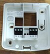
What I think is Yellow Live, Blue Neutral Red Switched Live goest to B and then a link from "right" L to A on the back plate
Is it how it should be?
That could very well be it.I'm not able to trace it.
What I think is Yellow Live, Blue Neutral Red Switched Live goest to B and then a link from "right" L to A on the back plate
Is it how it should be?
However, given the blue is connected to an earth terminal, we can't totally rule it out as an earth connection!
Many battery operated systems like yours don't require a neutral, and often the connection to neutral isn't made at the other end.
Lastly, we don't know what your boiler is. Some boilers can use (extra) low voltage thermostat switching, and not mains voltage; your new BDR91 requires mains.
Do you have any test equipment to help confirm any of the connections?
Great!I have multimeter
Are you happy to use it on mains voltages?
If so, with the meter on AC volts, and with one probe connected to an earth, check that either the red, or yellow is live at around 230V.
Measuring the blue wire, may give you a reading of a couple of volts.
Then confirm you are getting around 230V, between the Live and the blue wire.
That should (hopefully) confirm the connections.
D
Deleted member 267285
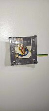
If blue was neutral yes, but as per @RandomGrinch it needs to be confirmed, as if you look on the Salus backplate, oddly, the earth isn’t connected, and what appears to be “neutral” is connected to the earth terminal. All you have is live and switched live, neutral isn’t required on Salus as it’s battery operatedI'm not able to trace it.
What I think is Yellow Live, Blue Neutral Red Switched Live goest to B and then a link from "right" L to A on the back plate
Is it how it should be?
I will do it tomorrow as I can't find a multimeter (facepalm) I'm guessing it's still somewhere in the boxes after the move.Great!
Are you happy to use it on mains voltages?
If so, with the meter on AC volts, and with one probe connected to an earth, check that either the red, or yellow is live at around 230V.
Measuring the blue wire, may give you a reading of a couple of volts.
Then confirm you are getting around 230V, between the Live and the blue wire.
That should (hopefully) confirm the connections.
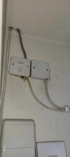
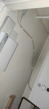
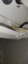
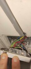
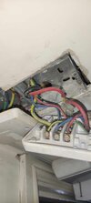
In the meantime, you can have a look at the pictures of the wiring that goes to the boiler, if that helps anything.
Attachments
D
Deleted member 267285
Unfortunately, those pictures don’t help much. You could put the receiver close to the switch for the boiler and use the switching wires from the Salus to the Honeywell.
I don't quite follow you.Unfortunately, those pictures don’t help much. You could put the receiver close to the switch for the boiler and use the switching wires from the Salus to the Honeywell.
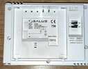
This is the picture of the Salus backplate and I intend to replace it with Honeywell. It is mounted downstairs in the living room.
Attachments
D
Deleted member 267285
The Salus will link back to the boiler, and looks like it does behind the switch, so rather than open up the boiler, the wiring could be done from the switch - make any more sense?
Looking at the photos, I'm fairly confident that this is the cable going to the thermostat (do you have a separate programmer anywhere?).In the meantime, you can have a look at the pictures of the wiring that goes to the boiler, if that helps anything.
...In which case, red is probably live, yellow switched live, and blue is connected to the neutral.
But as earlier, test with the multimeter to confirm.
As the BDR91 is an RF receiver, it can be mounted anywhere reasonable.I don't quite follow you.
As you have all the wiring by the boiler, @CBW has suggested it could be mounted there instead.
Sorry if this seems long winded, but being on the other side of the internet, we can not with good conscience just say 'shove the wires in and hope!'
")
And I do appreciate that everyone thinks about safety first especially we are talking about high voltage.Looking at the photos, I'm fairly confident that this is the cable going to the thermostat (do you have a separate programmer anywhere?).
...In which case, red is probably live, yellow switched live, and blue is connected to the neutral.
But as earlier, test with the multimeter to confirm.
As the BDR91 is an RF receiver, it can be mounted anywhere reasonable.
As you have all the wiring by the boiler, @CBW has suggested it could be mounted there instead.
Sorry if this seems long winded, but being on the other side of the internet, we can not with good conscience just say 'shove the wires in and hope!'
I managed to get a multimeter and like you have said, red live, yellow switched live, blue neutral.
Unfortunately after connecting the programmer like that it wasn't working, which annoyed me a lot.
So I did old-fashioned testing and I cut the power cord and connected the programmer to the power socket and it worked.
So I connected the bulb to wires from the old thermostat coming out from the wall and it was dead.
I have traced back the wires to the boiler and the neutral cable was cut inside the boiler.
After connecting neutral in the boiler and connecting the programmer, everything works fine
Thank you all for help.
Good, logical, fault finding.
Well done, I'm glad you got it working!
Well done, I'm glad you got it working!
DIYnot Local
Staff member
If you need to find a tradesperson to get your job done, please try our local search below, or if you are doing it yourself you can find suppliers local to you.
Select the supplier or trade you require, enter your location to begin your search.
Please select a service and enter a location to continue...
Are you a trade or supplier? You can create your listing free at DIYnot Local
Similar threads
- Replies
- 16
- Views
- 9K
- Replies
- 10
- Views
- 1K