
Need wiring for Timer as wire came off and don't know where to put back.

You are using an out of date browser. It may not display this or other websites correctly.
You should upgrade or use an alternative browser.
You should upgrade or use an alternative browser.
Hotpoint Dryer TCAM80 CGZUK Wiring
- Thread starter goldgrove
- Start date
Yes, the thing is I did not remove the wires but one came off during movement of the front panel.
I need to figure out which ones go to the start switch.
Serves me right for not taking a photo before doing any work.
I need to figure out which ones go to the start switch.
Serves me right for not taking a photo before doing any work.
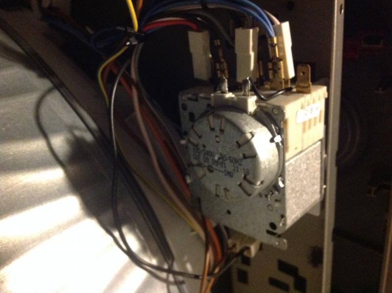
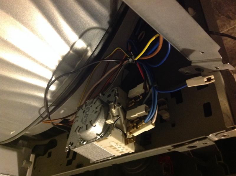
Sorry don't understand. The problem is 2 wires are missing for the start switch, I suspect it was put on the timer by mistake. The Red wire at bottom of Timer goes to the motor.
Lower Black wire goes to Grey wire, this is a double connector with two Grey wires.
One Grey goes to motor, The other one goes to the left hand side of the dryer looking from front.
Upper black wire from motor goes to unused terminal at top of timer in photo.
One Grey goes to motor, The other one goes to the left hand side of the dryer looking from front.
Upper black wire from motor goes to unused terminal at top of timer in photo.
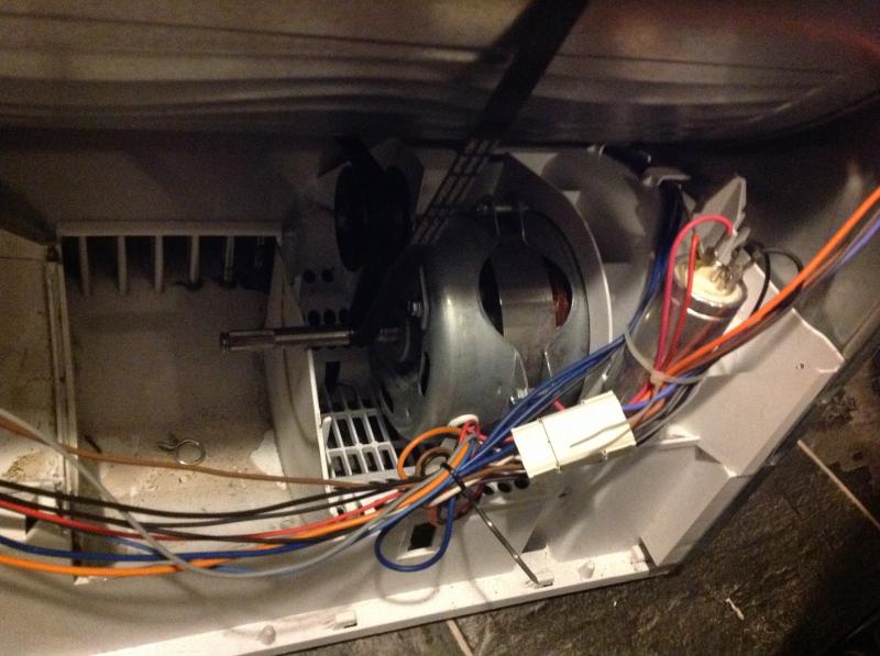
This was working, the belt broke, this is why I dismantled it, the wires got put back in the wrong place because of my not noting where the wires went.The problem now is that I can't figure out which wires go to the start switch. I have a Black and brown going to the heat switch as they are of the required length to reach it.
All the other wires are too short to go anywhere else. I tried it with BN / BL but it tripped the breaker. This is when I moved the BN/BL to the Heat switch. Have not tested since then as don't know which wires go to the start switch.
All the other wires are too short to go anywhere else. I tried it with BN / BL but it tripped the breaker. This is when I moved the BN/BL to the Heat switch. Have not tested since then as don't know which wires go to the start switch.
Thanks will try tomorrow and let you know, appreciate all the help.
This forum is better than Fixya. If you need any help with computers let me know as this is my area of expertise.
One other point, the Deep Blue wire that is shown disconnected (Fig 3) which is from the mains, is this going to the Timer the one at the top connected to the motor. From your previous post it is going to the motor.
Will check tomorrow and remove the blue and grey from timer to the start switch.
All working now, thanks very much guys.
Blue / Grey to Start switch.
Dark Blue to Top of Timer (going to motor)
Blue / Grey to Start switch.
Dark Blue to Top of Timer (going to motor)
DIYnot Local
Staff member
If you need to find a tradesperson to get your job done, please try our local search below, or if you are doing it yourself you can find suppliers local to you.
Select the supplier or trade you require, enter your location to begin your search.
Please select a service and enter a location to continue...
Are you a trade or supplier? You can create your listing free at DIYnot Local