Old Thermostat/Programmer

Joined
10 Oct 2018
Messages
2
Reaction score
0
Country
United Kingdom
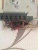
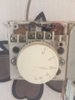
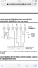
Hi guys, my first post on here and I’m helping somebody can help me to understand the wiring on my thermostat & programmer. I’ve been toying with the idea of getting new and updated programmable thermostat, when I’ve been looking at different ones, it got me curious about the wires that were in my current stat & programmer. The thermostat I understand, it’s just 2 wires which goes into a fuse spur, comes out the other end and goes into terminal 1 & 2 of my Baxi boiler. I understand that makes a circuit when there is demand. I have an old Danfoss Randall 103E programmer, and this is where it’s confusing me. From the fuse spur in the boiler cupboard, I have a cable going into another fuse spur downstairs, then a cable coming out of that into the programmer, so I know that’s my E L N. Then I can’t make heads or tail of the rest of the wiring, there are lots of cables running up the wall and don’t appear upstairs near the boiler, so what would they connect to? I assume they’re all under the floorboards which will be a pig to get to look at. I don’t understand the instructions either. Could anybody with more knowledge than myself be kind enough as to explain to me what does what? It’s been annoying me for 3 days I don’t really need to know because I’d opt for wireless as new, but it’s bugging me!!
Thanks in adv..
 

Attachments

  • DF1CA22D-6786-4858-9C5E-E88DAF5EDA17.jpeg
    DF1CA22D-6786-4858-9C5E-E88DAF5EDA17.jpeg
    201.8 KB · Views: 258
  • 9E6398D2-01F8-4952-A6FE-00E5DEC46487.jpeg
    9E6398D2-01F8-4952-A6FE-00E5DEC46487.jpeg
    206.9 KB · Views: 287
  • 4EB06AD1-F5FD-42F3-93C2-AAC079031FDA.png
    4EB06AD1-F5FD-42F3-93C2-AAC079031FDA.png
    153.2 KB · Views: 266
Sponsored Links
The thermostat I understand, it’s just 2 wires which goes into a fuse spur, comes out the other end and goes into terminal 1 & 2 of my Baxi boiler.
There are different ways it could be wired -
one wire from the boiler and back to the boiler, or
one wire comes from the programmer to the thermostat and then (to a motorised valve and then) to the boiler.

I understand that makes a circuit when there is demand.
Yes.

I have an old Danfoss Randall 103E programmer, and this is where it’s confusing me. From the fuse spur in the boiler cupboard, I have a cable going into another fuse spur downstairs, then a cable coming out of that into the programmer, so I know that’s my E L N.
Firstly - cables are spurs, what you are refering to are Fused Connection Units (FCUs).

There should be one which controls power to all of the heating system. As you have two means that someone could have done all sorts of things with the wiring.

Do you have a mid-position valve (3 ports) or one or two 2 port valves?
A hot water cylinder or a combi-boiler?
 
No need to answer the questions. I should have looked at the pictures first.

Yes,
FCU >>> Danfoss >>> boiler,

or

FCU >>> Boiler >>> Danfoss >>> back to boiler.

Cannot tell where the second FCU is.

Possibly

FCU >>> boiler
AND
FCU >>> Danfoss >>> Boiler
This would not strictly speaking be correct as it does not have ONE point of isolation.
 
Sponsored Links
You need to start at the boiler, for a thermostat there are three options.
1) 230 volt two wire connection.
2) Extra low voltage two wire connection.
3) Connection to the bus.
With the programmer it can be connected to same two wires as thermostat, or it can be independently wired.

Old thermostats often need a neutral as well to reduce hysteresis however some times it is better if there is a large difference between on and off temperatures.

So next consider what your thermostat does? In this house the thermostat is there to stop the boiler cycling, it does not set the temperature in the rooms, the thermostat radiator valve (TRV) sets room temperatures. However in my last house which was open plan, the programmable thermostat set the temperature down stairs, and the TRV's stopped upstairs getting too hot, and house before that had hot air central heating so air was circulated room to room so only one thermostat was required.

There are also complex systems where the electronic TRV head talks to a central thermostat (hub) which in turn tells the boiler what to do. So this house thermostat in the hall which is the last area to get warm, as the radiator in the hall is set that way, so in the winter thermostat does not turn off. The boiler modulates as the return water gets warmer, so is in essence controlled by the TRV and bypass valve, but without a thermostat in Spring and Autumn the boiler would be cycling all the time.

I looked at Wave which for my Bosch boiler is the only option for a thermostat connected to the bus, however this house has 5 radiators down stairs and 6 upstairs all separated by doors, so a single thermostat is useless. All is controlled by TRV's 7 in all, two electronic and 5 standard type, I intend to get more electronic heads.

Had my Boiler not been Bosch, then I may have been able to use OpenTherm in which case EvoHome would have been a good option. However since I do have Bosch which will not work with OpenTherm I have to use a Heath Robinson set up, not perfect, but good enough.
 
Hi, thanks very much for taking the time to reply.
The boiler is in a cupboard upstairs, I have two thick cables going into the FCU then coming out I have 2 smaller white cables. Which are the L N E for the boiler, and the 2 connections for the Honeywell Thermostat which is downstairs, Then I have 5 of the bigger cables coming downstairs, I’m guessing 2 from the FCU Because one of them connecting straight into the thermostat.
The other one connects into another FCU on the wall behind thermostat and programmer, then I have the other 3 connecting straight into the programmer
 
Not sure you need one point of isolation? My system has four supplies, pair of batteries in two electronic TRV heads and a thermostat, and a 5 volt USB supply to hub, and a FCU to boiler.
 
Hi, thanks very much for taking the time to reply.
The boiler is in a cupboard upstairs, I have two thick cables going into the FCU then coming out I have 2 smaller white cables. Which are the L N E for the boiler, and the 2 connections for the Honeywell Thermostat which is downstairs, Then I have 5 of the bigger cables coming downstairs, I’m guessing 2 from the FCU Because one of them connecting straight into the thermostat.
The other one connects into another FCU on the wall behind thermostat and programmer, then I have the other 3 connecting straight into the programmer
Tried to work out what you have, would guess "two thick cables going into the FCU" is the feed to it as part of a ring, but after that can't work it out.
 
Depends how you read the regulations.

While local isolation might not be a requirement, if there is a local switch which might be taken as being for this purpose, I would say that it should disconnect all of the items of the system.
 
The thermostat I understand, it’s just 2 wires which goes into a fuse spur
The thermostat is just an on/off switch and yours is wired up using only live wires. The live supply should come in from your Danfoss Randall 103E timeswitch to the thermostat terminal (1) So when the programmer is set to be 'on' terminal (1) of the thermostat will also be 'on' (or live).

If the thermostat has determined that heating is required it will have operated its own internal switch which joins terminals 1 & 3 together. Terminal (3) will now become live, and as it is connected to your heating system, so the heating will operate. When the room temperature reaches the value set on the dial, the switch opens, switches off terminal (3) and the heating along with it.

Unfortunately, your thermostat is not wired in correctly. It is a mechanical thermostat with old technology and by the nature of its design, it is not particularly accurate. To improve things they have a built in device known as an 'accelerator' which is a small heater that encourages it to switch on and off more quickly. However, for this to work it should have a neutral connection to terminal (2). But as you can see in your photo, it is missing.

9E6398D2-01F8-4952-A6FE-00E5DEC46487.jpeg

OK, it will work in a fashion, but it won't be particularly accurate and you will probably notice a change in the room temperature between it switching on and off.

I’ve been toying with the idea of getting new and updated programmable thermostat
At the moment, you have a separate programmer and thermostat, so if you are going to install a programmable thermostat that has both time and temperature control combined, it will replace both of them, and the wiring would need re-configuring as the 'two' devices become 'one'

There are 5 different wiring configurations for different types of heating system in the 103E instructions. I notice that you have posted the wiring diagram for a 'combi boiler' so assume that is what you have. However, if you have one of the other systems shown ie with stored hot water (a hot water cylinder), and / or motorised valves, more would be involved.
 

DIYnot Local

Staff member

If you need to find a tradesperson to get your job done, please try our local search below, or if you are doing it yourself you can find suppliers local to you.

Select the supplier or trade you require, enter your location to begin your search.


Are you a trade or supplier? You can create your listing free at DIYnot Local

 
Sponsored Links
Back
Top