Anyone Familiar with Internal Wiring of Boilers? (sorted)

Joined
27 Nov 2007
Messages
120
Reaction score
0
Location
Manchester
Country
United Kingdom
I'm trying to connect my new thermostat to my Icon 23T boiler. Thermostat is of volt-free type and the boiler MIs say there should be a "white external controls cable" that is bridged for connecting a thermostat.

All makes sense. I've opened the control panel to expose the PCB and there is a white two core flex cable. One terminal connected to the built in timeclock, and the other going to a multiplug.

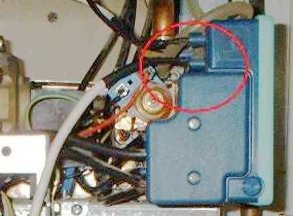
The thing is, the other end of this cable is connected to what looks like the ignition module. If I unplug it from there, the boiler fails to spark.

I'm totally confused. This is the only cable that the MIs refer to. The only other white wires go to a temperature sensor on one of the flow pipes.

Any ideas where to start? Maybe the white cable I describe should just be free ended when a thermostat is not in use, but someone connected it up to the ignition module? The thing is, this cable is really long and just looks like it should be for an external thermostat control unit.

I can get some pictures of the board if that helps?
 
Sponsored Links
Don’t know this model by heart, is that an ideal?
Never seen a boiler that has a wire built in for a stat, always connects on a terminal strip.
Have you identified the connection point correctly?
 
I don't have a manual for your boiler (shock hotrror!!) but the thermostat connections would normally be linked together, if there's no stat. The thermostat would be disconnected by the timer, so it sounds like that's the white wire they mean.
There would be a terminal strip where you could connect the external stat, on every boiler I've seen!
 
Boiler is badged up as an Icon, but made by Hermann.

The white cable seems to match the description in the boiler's handbook, but it completely throws me as to why it's connected to the ignition module. It's obviously doing something, as the burners get no spark if you unplug it.

Doesn't look like it should be plugged there though, as there is already a HT lead and a flame sensor lead plugged in :confused:

I'll take some pictures of the PCB tonight and show you the user manual too, as something isn't right.

Thanks very much for your replies.
 
Sponsored Links
Okay, here are some pictures:

This one shows the white cable coming out of the control unit. The red ring shows how it connects for some reason into the ignition module.
Notice how excessively long the cable is, suggesting it was not meant to plug in there (there's about another meter length of it dangling down outside of the picture).
Boiler1.jpg


Next one is close up shot of PCB. I've highlighted the two places the two cores of the white cable go to. The one on the right-hand side of the picture is directly behind the mechanical timeclock.
Boiler2.jpg


Finally, user instructions on how to connect a thermostat.
Boiler3.jpg


So, from what I can see, I seem to have the right cable as mentioned in the instructions, but the boiler will not fire if I remove it from the ignition module.

Hopefully someone can help me out?
 
Just to add, when the boiler is on, that cable is actually live with 240v. Weird as the cores are very small and the other end into the spark unit just has a blanked off spade connector with black sheathing over it.
 
Are the terminals on the inition module just somewhere to "park" and short the connectors on the end of the white cable?

Although they say voltfree I suspect one wire is 230V and the other the switched live to trigger the heating.

Have a look at the ignition module - you may find the two terminals just short together and don't have any connection with the module circuit.

Have a look at Hermanns Italian site - there's a UK contact number for the importer.
 
Yeah good point, could be just a parking place for the connectors. There are two connection points on the ignition module labelled "spark". It will only ignite the boiler when the white cable is plugged into the bottom one. If you look at the first picture, you can see the two connectors on the unit. There's another one in the background, but this is for the flame sensor.

One wire of the two in the white flex is certainly mains live. If it was described as "volt-free" I would have expected there to be only around 24 volts max across the terminals. :confused:

When the white cable is parked in the ignition module, could it be artificially providing an earth or a supply to the unit, and making it function properly, but in actual fact, there is a cable missing. Hence, when I remove the white cable, the ignition module fails to function properly?

Thanks for you help!
 
At one stage Hepworth Heating (now part of the Vaillant group) has a share in Hermann and were dealing with the spares/support side.

I think these were another builders merchant only boiler ie generally illegally installed on very poor systems. The only one I've ever come across was in such a poor state I refused to look after it. I think the boiler itself was no worse than other low cost boilers. Just a problem with support and backup.
 
Here's the top end a bit clearer
Cable1.jpg

but I can't tell from the other pic exactly where the wires go.
What colours are the wires inside the white insulation?

I DO have the manual - I clicked on Ikon not Icon!


LIke I said, the thermostat has in effect to be in series with the clock, so the ignition and CONTROL box as it's called, is the right place. Not sure if you can connect to the were the T.A> treminals are shown. If not, you can cut into the wire shown, anywhere along it.
Cables2.gif
 
The wires inside the white flex are both black.

So from your wiring diagram, the T.A terminal should be bridged at the moment then and I need to run a separate cable to use these two terminals?
 
Okay, getting a little closer now. Some more pictures here:

These are the two cores of the white cable that connect into the boiler PCB. As you can see, both have terminal blocks on them. If I disconnect the blue connector on the left, the boiler clicks off, as I guess it breaks the timeclock circuit. So I take it these are the two terminals I need to have my thermostat between? Doesn't correspond with the boiler MIs though. What is the black plug for on the left??
Boier4.jpg


The wire with the black plug connects here, which corresponds to terminal 3 on the connector block, from your wiring diagram.
Boiler5.jpg


The wire with the blue plug connects here, corresponding to the wire you say to cut.
Boiler6.jpg


So, I think I run a new 2 core flex from the thermostat control with spade connectors on the end, and connect them to the terminal blocks with the blue plug?

Cheers
 
Managed to get it running this afternoon. Wired it in using a length of 4-core flex - tapping off the boiler's main supply and connecting the the two switched terminals between the black wire with blue plug on.

Working like a treat now.

Thanks for all the input guys. Oh and Chris, that wiring diagram was really useful.

Thanks again :)
 
One last thing, I noticed this on the wiring diagram (circled)
Boiller7.gif


Notice how ignition control unit should have 3 connections - Ignition Electrode, Flame Sensor and EARTH.

So I bet the control unit was getting an earth via the PCB. What I should have done was connect up an earth to the free terminal the white cable was parked in, then the unit should have fired the boiler up properly and I could have used the nice long white cable.

Oops :mad: Never mind, it's done and put back together now.
 
Hello, Thank you to all the previous respondents - you have helped me locate the two cables for the volt-free thermostat switch.

Now, please could you advise how to connect the live and neutrals to power the thermostat switching module (for a drayton MiStat wireless thermostat). It requires 230V AC fused 3A. Can I source this from existing wiring inside the boiler or do I have to hard-wire this independently?

Any advice would be gratefully received.

Thanks!
 

DIYnot Local

Staff member

If you need to find a tradesperson to get your job done, please try our local search below, or if you are doing it yourself you can find suppliers local to you.

Select the supplier or trade you require, enter your location to begin your search.


Are you a trade or supplier? You can create your listing free at DIYnot Local

 
Sponsored Links
Back
Top