
- Joined
- 4 Nov 2019
- Messages
- 3
- Reaction score
- 0
- Country

A friend recently started to have problems with his central heating system (CHS).
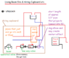
There are two boilers, being an oil fired boiler and pump (P2) in an outhouse and a back boiler around the living room fire. There is a second pump (P1)which is in the Airing Cupboard.
Each pump has its own thermostat and whilst P1 in the Airing Cupboard has a manually operated electrical switch the pump in the outhouse, P2, is wired so as to come on with the oil fired boiler.
My friend was told NOT to run both pumps simultaneously as they interfered with one another.
The visible plumbing for the CHS is depicted in the attached diagrams, the remaining CHS plumbing is buried under the bungalow's floor or in the walls.
The radiators seem to be in parallel with one another i.e. they all warm up simultaneously and shutting off any combination of radiators does not effect the remaining radiators.
Given the size and number of connections to the hot water tank (HWT) I assume there are two heating coils in the HWT, is this usual? However we do not know how the left hand heating coil is connected to the rest of the CHS.
We found the 1/2"? venturi? pipe in the Airing Cupboard to be clogged, after scraping out the sediment in that pipe the back boiler no longer "boils".
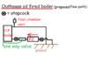
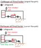
My friend wanted to change the corroded and seized stopcocks in the outhouse and I noticed that P2 was drawing from the bottom of the boiler. In what may turn out to be a Homer moment I suggested that it might be better to reverse P2 so that it feeds the bottom of the boiler and we added a oneway valve.
At the moment the oil fired boiler now rapidly trips its thermostat (which it did not previously do) and I suspect that when the oil fired boiler and its pump are running the new flowpath is trying to push water the WRONG way through the one way valve in the airing cupboard.
Although we are uncertain whether the flowpath from the oil fired boiler has an as yet undislodged air lock I suspect that what we/I should do is reverse the connections to the boiler, as depicted in the diagram "Outhouse oil fired boiler (proposed flow path)", so as to draw from the top of the boiler rather than the bottom of the boiler yet restore the original flow directions in the plumbing connecting the outhouse to the bungalow.
Suggestions as to the fix for the current situation would be most welcome as would a likely diagram for the whole system.
Thank you.
Probably Homer.
There are two boilers, being an oil fired boiler and pump (P2) in an outhouse and a back boiler around the living room fire. There is a second pump (P1)which is in the Airing Cupboard.
Each pump has its own thermostat and whilst P1 in the Airing Cupboard has a manually operated electrical switch the pump in the outhouse, P2, is wired so as to come on with the oil fired boiler.
My friend was told NOT to run both pumps simultaneously as they interfered with one another.
The visible plumbing for the CHS is depicted in the attached diagrams, the remaining CHS plumbing is buried under the bungalow's floor or in the walls.
The radiators seem to be in parallel with one another i.e. they all warm up simultaneously and shutting off any combination of radiators does not effect the remaining radiators.
Given the size and number of connections to the hot water tank (HWT) I assume there are two heating coils in the HWT, is this usual? However we do not know how the left hand heating coil is connected to the rest of the CHS.
We found the 1/2"? venturi? pipe in the Airing Cupboard to be clogged, after scraping out the sediment in that pipe the back boiler no longer "boils".
My friend wanted to change the corroded and seized stopcocks in the outhouse and I noticed that P2 was drawing from the bottom of the boiler. In what may turn out to be a Homer moment I suggested that it might be better to reverse P2 so that it feeds the bottom of the boiler and we added a oneway valve.
At the moment the oil fired boiler now rapidly trips its thermostat (which it did not previously do) and I suspect that when the oil fired boiler and its pump are running the new flowpath is trying to push water the WRONG way through the one way valve in the airing cupboard.
Although we are uncertain whether the flowpath from the oil fired boiler has an as yet undislodged air lock I suspect that what we/I should do is reverse the connections to the boiler, as depicted in the diagram "Outhouse oil fired boiler (proposed flow path)", so as to draw from the top of the boiler rather than the bottom of the boiler yet restore the original flow directions in the plumbing connecting the outhouse to the bungalow.
Suggestions as to the fix for the current situation would be most welcome as would a likely diagram for the whole system.
Thank you.
Probably Homer.
Attachments
Last edited:
