Magic setting for a pressure diff valve?

Joined
22 Mar 2014
Messages
291
Reaction score
7
Location
Devon
Country
United Kingdom
I've no real problem as such just questions.

I've a heating circuit fed off a ESBE mixer valve, flow and return back to the boiler, TRV's on all radiators, All TRV's connected to the flow. Pump for the circuit is a Grundfos alpha2.

As I've got TRV's on every radiator I've fitted a pressure differential valve. This is adjustable 0.1-0.5bar.

Is there a proper way to set this up? I've put it half way, all radiators get warm, pump seems happy and nothing bad is happening.
 
Sponsored Links
Do you mean an Automatic Bypass Valve, fitted between flow and return just after the pump?

If so, what setting is the Pump on?

Why no room stat?
 
Hi

I think they work the same, if pressure on one end is more than the preset limit on the valve it opens to form a connection?

I've been playing with the pump, running it on the third triangle on the auto side. Although I might run them on setting two.

I have a room stat also, the pump runs on for 30mins after the stat has enough in room stat mode.
 
Just leave the pump on Auto and no need for a by pass.
 
Sponsored Links
Just leave the pump on Auto and no need for a by pass.

I'm not 100% sold on the auto aspects to be honest. I think If I turn the valves up to 0.5 bar then set the pumps to auto mode that suits it should give me the best of both worlds.

Just considering all options really.
 
I think they work the same, if pressure on one end is more than the preset limit on the valve it opens to form a connection?
But is the valve in a link between flow and return? If not, where is it?

I've been playing with the pump, running it on the third triangle on the auto side. Although I might run them on setting two.
Have you balanced the system?


I have a room stat also, the pump runs on for 30mins after the stat has enough in room stat mode.
Is the TRV in the room with the room stat set to max?

Which boiler do you have?

Is the whole house included in the circuit fed from the Esbe valve? If not, can you provide details of the complete system?

Hi

System is balanced, heats up very equally. The room stat is at one end of a corridor, a radiator with TRV at the other. TRV is set a few 'rings' below max.

The house has 2 circuits at the minute. Both are 100% separate with flow and returns going back to the boiler, both off ESBE mixer valves.

The boilers software controls all the circuits. I can run the heat in a few ways..
Room stat/Weather comp via external sensor/both/constant flow. Being from the UK I cant sit 100% happy with weather comp as i'm/we're use to having heat come on high, not modulated.

The whole heating system is new, 16 radiators, a 50/50 mix of stelrad and new cast iron ones.

The Differential valves are before any radiators.

Boiler is an Effecta biomass boiler. 35kw with intergrated HW coil.

http://www.rainbowheatandpower.co.uk/resources/Effecta_Komplett_III_leaflet.pdf
 
If you have a by-pass fitted it should be across the pump/s in your case.
Part of the idea of the auto mode is reduced power consumption.
So if it uses the by pass you'll be using extra power unnecessarily.
 
If you have a by-pass fitted it should be across the pump/s in your case.
Part of the idea of the auto mode is reduced power consumption.
So if it uses the by pass you'll be using extra power unnecessarily.

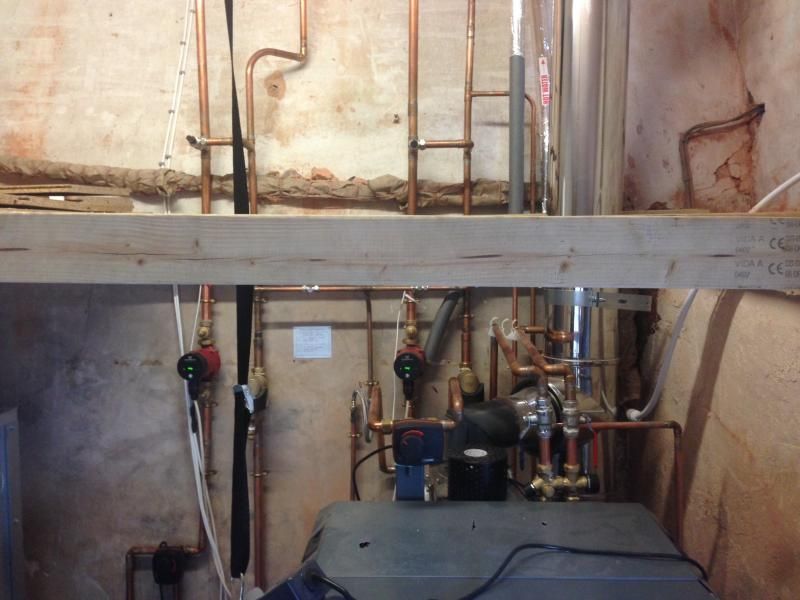
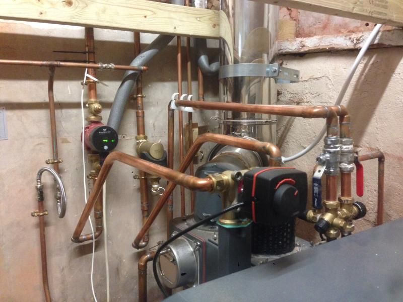
The valves are right after the pumps, forgive the mess in the pics, I've got to take down the wooden frame and remove the old pipes still!

I put the valves in, incase I wasn't happy with how the pumps work on auto, however the boiler seems too smart for its own good with the ESBE valve control and in weather comp or 'both' mode it shouldn't need them. For the sake of £25 though it seemed prudent to cover every eventuality.

I'm struggling to see how the pump measures pressure changes though and how I can get the best from that.

you can see them at the top of the pic above the frame


This is how the zones are fed

 
Two ESBE 3 port mixing valves?
Does each one have an independent indoor sensor?
 
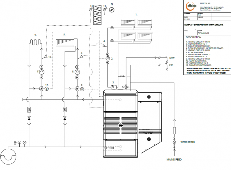
I'd have piped it as per the factory diagram here....
//www.diynot.com/diy/threads/boiler-circuit-drawing.418358/

And standard ZV's for each zone.
Unless an ufh circuit was involved and needed separate blending.

If your boiler controller can control another two 3 port mixing valves then surely it would have been simpler to just allow it to control the esbe TM valve to give the compensated output?

I assume thats just a "constant temperature" actuater head fitted on the TM valve?

It is piped as per the factory diagram.....


The esbe valves are suppose to be much more efficient than a zone valve, They do give a compensated output as they are at the minute, I've not said they don't, they're constantly adjusted by the boiler, there's zero operational issues with the heating. There's a flow temp sensor after the pump on every circuit. It allows each zone to have differing heating characteristics. Zone valves in comparison seem very inefficient.
 
When the UFH circuit is operating or the other rad circuit, what prevents them from flooding the boiler return with low return temperatures?

It looks as if the important "shunt" TM esbe 4 port valve has been by passed.
 
When the UFH circuit is operating or the other rad circuit, what prevents them from flooding the boiler return with low return temperatures?

It looks as if the important "shunt" TM esbe 4 port valve has been by passed.

Yes, looks like it but the 'back end' protection is in the boiler. Its also selectable on/off which is dangerous. I did think the same as I asked the question. Its to do with the hot water coil inside, its a simpler way of providing protection against 'shock cooling' all round against water and heating circuits.
 

DIYnot Local

Staff member

If you need to find a tradesperson to get your job done, please try our local search below, or if you are doing it yourself you can find suppliers local to you.

Select the supplier or trade you require, enter your location to begin your search.


Are you a trade or supplier? You can create your listing free at DIYnot Local

 
Sponsored Links
Back
Top