

Hi again
I wonder if anyone would be so kind as to check out the circuit diagram below and let me know
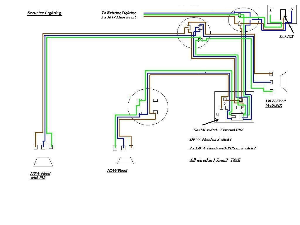
a) if it acceptable to link the common terminals in the switch in this way ? and
b) If there is a better way of acheiving the same effect ? ie How would you do it ?
The security lights are to be fitted to the outside of my garage and I am opting to tap into the existing lighting circuit which consists of 2 x 36W Fluorescent fittings only. The existing wiring is fed from a 5A MCB in the garage CU. There is nothing else on the circuit
The switch is also going to be outside and I plan to utilise an IP rated double (2 way) switch that I already possess. (Hence the extra L2 in the diagram)
All thoughts appreciated
Regards
MGFDude
Edit - Spelling
I wonder if anyone would be so kind as to check out the circuit diagram below and let me know
a) if it acceptable to link the common terminals in the switch in this way ? and
b) If there is a better way of acheiving the same effect ? ie How would you do it ?
The security lights are to be fitted to the outside of my garage and I am opting to tap into the existing lighting circuit which consists of 2 x 36W Fluorescent fittings only. The existing wiring is fed from a 5A MCB in the garage CU. There is nothing else on the circuit
The switch is also going to be outside and I plan to utilise an IP rated double (2 way) switch that I already possess. (Hence the extra L2 in the diagram)
All thoughts appreciated
Regards
MGFDude
Edit - Spelling

