System pumping over

iep

Joined
5 Apr 2010
Messages
417
Reaction score
11
Country
United Kingdom
While hunting down the cause of corrosion in our open vent system I found that we have some 'pumping over' going on. It does not happen all the time but can be made to happen continuously if the pump is set on its highest speed. Normally we only run the pump on its medium setting but even then it seems to occur occasionally.

To test this I put a small plastic tub inside the F&E tank below the vent. When I checked it this moring, it was full.

When the pump on full speed a constant stream of water is produced at the vent.

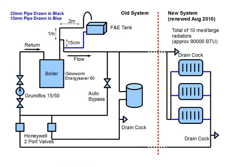
Below is a diagram of our system including a few measurements of the pipework around the F&E tank.


Can anyone suggest why the pumping over might be occuring?

Cheers,

iep
 
Sponsored Links
Your system is now considered to be configured incorrectly.The pump should be after feed/vent connections to your system and then the bypass and then the motorised valves in that order.you may also have a partially blocked cold feed causing water to be forced up vent.Either way it involves a bit of repipeing.
 
Yes, I wondered about that. Moving the pump from the return to the flow side (after the cold feed and vent connections) is reasonably easy but moving the motorised valves from the return to the flow side is not really an option whitout some fairly major work (removal of half the kitchen).

If the pump were moved to the flow side of the boiler but the moroised valves left where they are, would that be a problem?

iep
 
Sponsored Links
The pump is definitely as I have drawn it.

Cheers,

iep
 
No that would be worth a try and while you are doing it check the feed
/vent connections for blockages.It should work and stop pumpover.
 
Ideal, thanks.

Just for clarity, when you say that there might be a blockage on the cold feed/vent connections do you you mean effectively a blockage on the main flow pipe between those connections (where I have written 15cm)? This is the only way that I can see water pumping up the vent and then returning to the system via the cold feed.

Additionally, I have read that you can sometimes tee off the vent pipe at the F&E tank and connect this to the cold feed output of the tank (effectively using the vent pipe as both vent and cold feed)? I can see why this would stop pumping over and, if it is possible, would be a very easy thing to do.

Cheers,

iep
 
Where your 15mm feed joins the 22mm is where to expect a blockage.Yes you can do away with a vent pipe and replace the 15mm pipe from the f/e tank with a 22mm pipe the open end of which is always below the water level and prevents air being sucked in.Be aware that this configuration can only be applied to boilers that have overheat protection built in to its controls.See boiler MI's for info on this.No valves whatsoever should be fitted to the new feed/vent pipe.
 
  • Thanks
Reactions: iep
Thanks gaman, that is very, very useful info.

The link below is to the manual for our boiler. It mentions an overheat cut out so I am pretty sure this is the feature you are referring to? If you have time to take a quick look and check this it would be much appreciated.

http://www.glow-worm.co.uk/stepone/data/downloads_sd/58/00/00/energysaver60.pdf

In that case my plan would be:

1. Replace pipe between boiler flow output and bypass valve to remove any potential blockages in this part of the system.

2. Remove 15mm cold feed and hook up F&E tank to new 22mm pipe which I would connect at the highest point on the flow side of the boiler.

If this worked then I would hopefully not have to move the pump?

Thanks,

iep
 
This won't answer your problem :( 
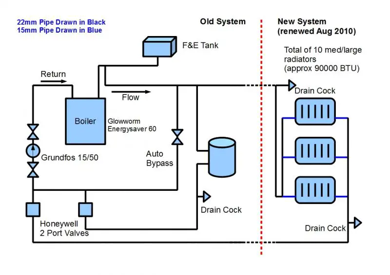
but are the flow and return really connected to the radiators as shown, i.e the flow connects at one end of the "ladder" and the return at the other?

If it is you have created a Tichelmann system. The advantage of this is that the total pipe length is the same for each radiator. So the pressure differential is the same for each rad, which makes balancing much easier.

Tichelmann systems are use more in commercial installations.

View media item 1210
 
Hi D_Hailsham. Unfortunately, it is not quite like that. Space constraints and the shape of our house meant that the actual system ended up looking looking more like this:


As you point out, balancing is much harder to achieve as the rads furthest from the main flow connection see much less pressure. I compensated for this by using massive rads that work well even with a larger temp drop across them. It's not ideal but does work okay.

I am planning to add another couple of rads next summer though and might lok at making the modification that you suggest.

Cheers,

iep
 
Gasman, just to be sure I understand, you think this system might be okay provided I replace the pipework between the boiler and bypass valve on the flow side?


Cheers,

iep
 
That last configuration would work but you still need to move the pump and using your drawing fit it above the word flow if you understand.
 
  • Thanks
Reactions: iep
Great thanks.

I'm happy to move the pump (it's very easy to do in our system) but, purely out of curiosity, what would be the issue with leaving it where it is?

I'm not questioning the advice as I was surprised to see it in that location myself but, given it is a circulating pump (and so pulls and pushes water round the system in equal measure), what is the issue with pumping on the return side rather than the flow?

Cheers,

iep
 
It probably won't make a difference left where it is but to be correct it should be moved to after the feed/vent connection so it is negative pressure applied to feed/vent.
 

DIYnot Local

Staff member

If you need to find a tradesperson to get your job done, please try our local search below, or if you are doing it yourself you can find suppliers local to you.

Select the supplier or trade you require, enter your location to begin your search.


Are you a trade or supplier? You can create your listing free at DIYnot Local

 
Sponsored Links
Back
Top