THE WORD "COMMON" in cental heating

The only thing I'm not sure of is with the programmer in between "ON" times if I turn the cylinder stat down from 65 to 45 and below the boiler fires up
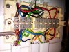
Something is still wired incorrectly, can you post a clear photo off the wiring connections at the wiring centre and at the programmer.
3 port valve comes on
What do you mean by this?
I have rechecked the wiring an I had the make on rise and break on rise in 6 & 7 in junction box instead of 7 & 6 both wrong way round
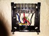
If you have wired it to the Honeywell standard Yplan wiring centre numbering, you have mixed up all the connections to the cylinder stat.

Common on the cly stat is connected to terminal 6 along with HW on from the programmer.

Make on rise/satisfied/2 on the cly stat is connected to terminal 7 along with HW off from the programmer and the grey wire to the valve.

Break on rise/call for heat/1 on the cly stat is connected to terminal 8 along with the boiler call for heat, pump live, and orange wire to valve.

I wish I was there, I could have sorted it by now!!
Y plan.png
 
Sponsored Links
Hi Echo the husky, I will take some photo's and check the wiring as you have said and if OK with you I will come back ASAP. Thanks for your help so far.
 
Hi Echo the husky, I've taken 3 photo's 0081 back plate to the programmer 0083 diagram on back of programmer 0085 the wires in the junction box. Hope you get them. Thanks again.


Attachments

  • IMAG0081.jpg
    IMAG0081.jpg
    239 KB · Views: 126
  • IMAG0083.jpg
    IMAG0083.jpg
    208.9 KB · Views: 113
  • IMAG0085.jpg
    IMAG0085.jpg
    223.5 KB · Views: 124
Why is room stat terminated into pump live/orange/boiler switched live???
 
Sponsored Links
The room stat is the 4 wires going up the middle trunking isn't it?

I was more concerned with all the damaged insulation and exposed copper!
 
Looks to me room stat is top far right?...not sure what the single grey core is that terminates into black core from programmer CH on..
Looks a fookin mess...
Edit...looks like boiler switched live..
 
I'm guessing that's the boiler, Black neutral, red switch live., the boiler is an ideal classic or similar 3 wire boiler IIRC from another thread. I think the round flex in the middle is feeding the electronic room stat, and sw live back and the odd grey/black stripe wire is the supply to the stats common contact, powered from the programmers Heating on.
 
The actuator in the mid port valve is a synchronous motor. Fed with AC voltage it will rotate the valve spindle against a spring return. When it reaches the end stop it stalls but continues to have AC voltage fed to it. (*) Turn off the AC and the spring rotates the spindle ( and the motor ) backwards to the other end stops.

To hold the spindle at the mid position ( HW and CH ) the motor is driven by AC to the mid point where a micro switch operates. The micro switch inserts a diode into the feed to the motor which means the motor now has a DC supply. This DC supply holds the motor stationary at the mid point. Without the DC supply the spring return would rotate the spindle back to the end stop.


(*) some actuators use DC ( micro switch and diode ) to hold the motor close to the end stop but wear and tear on the micro switch can mean the motor is held before the mechanical end stop and the port that should be closed at that end stop doesn't fully close

Aye, it's good to see plagiarism is alive, well & living in BGs computer.
 
Aye, it's good to see plagiarism is alive, well & living in BGs computer.

Sir Richard , please prove your accusation of plagiarism by telling people from where I copied that.

You can't because it was knowledge I acquired many many years ago.

EDIT Removed an image that somehow got into the post.
 
Last edited:
"You will find most RGIs from here cruising the Common at the weekend"
 
Hi Echo the husky, yes you have everything marked up right in the return picture, the odd grey/black stripe wire is from the room stat, I needed an extra wire when I replaced the room stat. Some of the wiring I will be replacing, it's all in an 18 inch wide cupboard, and on the left hand wall as you look in, so not a lot of room to work, but your blown up picture shows wires that need to be replaced. It's also very hard to fit 3 to 4 wires in the small connection blocks, wish they were one size up.
 
Hi Echo the husky, seems you where right, there was still wrong wiring, the common was in number 8 and should have been in number 6, all the stat wires are now correct and all is working well, and all the doggy wires have been replaced, it all came back to that word "COMMON". Thanks for your help.
 

DIYnot Local

Staff member

If you need to find a tradesperson to get your job done, please try our local search below, or if you are doing it yourself you can find suppliers local to you.

Select the supplier or trade you require, enter your location to begin your search.


Are you a trade or supplier? You can create your listing free at DIYnot Local

 
Sponsored Links
Back
Top