
You are using an out of date browser. It may not display this or other websites correctly.
You should upgrade or use an alternative browser.
You should upgrade or use an alternative browser.
wiring 2 loads up in in parallel to drop voltage (ed: he means in series)
- Thread starter AstonHill
- Start date
Sponsored Links
Sorry I`m struggling to see your intentions clearly here.
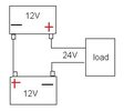
It seems one diagram shows two 12v batteries wired in series to provide 24V to one load.
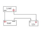
The other diagram shows one 12v battery wired up to two loads (or if you prefer two half loads) in series so they will both consume the same current but the voltage split will be dependant upon the equivalent resistance comparison of the loads. i.e. if both loads are exactly half of the total load then they will run the same current and at 6v each.
Of course I am assuming your loads are pretty much purely resistive in effect rather than rapid switching of coils/capacitors.
It seems one diagram shows two 12v batteries wired in series to provide 24V to one load.
The other diagram shows one 12v battery wired up to two loads (or if you prefer two half loads) in series so they will both consume the same current but the voltage split will be dependant upon the equivalent resistance comparison of the loads. i.e. if both loads are exactly half of the total load then they will run the same current and at 6v each.
Of course I am assuming your loads are pretty much purely resistive in effect rather than rapid switching of coils/capacitors.
Last edited:
Yes, each of the loads in the second image will get a proportion of the 12V.we wire the loads up in in parallel
If they both have the same internal resistance, they will each get 6Volts.
But in the real world, with real loads you have to be careful as their internal resistance can change giving interesting effects, for example providing more voltage to one over the other.
Sponsored Links
- Joined
- 4 Sep 2022
- Messages
- 584
- Reaction score
- 3
- Country

Yes that is what i want to do hear; is split the voltage in half for each load so they are 6V eachSorry I`m struggling to see your intentions clearly here.
It seems one diagram shows two 12v batteries wired in series to provide 24V to one load.
The other diagram shows one 12v battery wired up to two loads (or if you prefer two half loads) in series so they will both consume the same current but the voltage split will be dependant upon the equivalent resistance comparison of the loads. i.e. if both loads are exactly half of the total load then they will run the same current and at 6v each.
Of course I am assuming your loads are pretty much purely resistive in effect rather than rapid switching of coils/capacitors.
- Joined
- 4 Sep 2022
- Messages
- 584
- Reaction score
- 3
- Country
But will each one get 6VYes, each of the loads in the second image will get a proportion of the 12V.
internal resistance?If they both have the same internal resistance, they will each get 6Volts.
- Joined
- 4 Sep 2022
- Messages
- 584
- Reaction score
- 3
- Country
So is that how they get say a 24V DC supply down to 2V per LED; by having 12 lights wired up (series or parallel one not sure!)It has worked very well for many decades in thing like Christmas fairy lights.
BTW it is 2 times LED lamps I want to wire up to a car battery. The LED lamps take 4 AA batterys (so 1.5V times 4= 6V each)
They will if the two loads are (electrically) identical - which is what SFK was referring to when he talked of them having the same 'internal resistance'.But will each one get 6V
If the two loads are different, then they will share the 12V unequally (e.g. one might get 8V and the other 4V).
BTW, in your diagram, the two loads are in series, not parallel.
Kind Regards, John
- Joined
- 27 Jan 2008
- Messages
- 23,861
- Reaction score
- 2,699
- Location
- Llanfair Caereinion, Nr Welshpool
- Country
A LED is a current dependent device not voltage, putting a white LED across a 3 volt battery can cause thermal run away, so we put 3 LED's and a resistor in series across a 12 volt battery the resistor is called the driver, as it limits the current to within safe limits.
With AC we can use a capacitor as a driver which limits current, but then frequency becomes important.
We can use zener or avalanche diodes to limit the voltage where multi items are in series, but chips like the 78xx series are so cheap and now pulse width modulated chips, the old methods are not used that much any more.
He's talking about "LED lamps", designed to run off 4 x 1.5V batteries (i.e. 6V) (hence with a resistor or other current controlling something), not LED elements.A LED is a current dependent device not voltage, putting a white LED across a 3 volt battery can cause thermal run away, so we put 3 LED's and a resistor in series across a 12 volt battery the resistor is called the driver, as it limits the current to within safe limits.
Kind Regards, John
- Joined
- 27 Jan 2008
- Messages
- 23,861
- Reaction score
- 2,699
- Location
- Llanfair Caereinion, Nr Welshpool
- Country
How can one connect two pulse width modulated controllers in series? A battery often has quite a voltage range, typical 12 volt lead acid for example between 11.8 and 14.8 volt, and a AA battery 1.2 to 1.6 volt, depending on type, supplying an extra low voltage light from a power supply the voltage is reasonably stable so 11.8 to 12.2 typically for a nominal 12 volt supply, but with a battery LED lamps are more expensive, for cars the bulbs often rated 10 - 30 volt and there is inside the bulb rectifiers and switch mode controllers, and to put two 12 volt bulbs in series on a 24 volt supply could cause all sorts of odd results.He's talking about "LED lamps", designed to run off 4 x 1.5V batteries (i.e. 6V) (hence with a resistor or other current controlling something), not LED elements.
Kind Regards, John
I have used a 7812 chip with a red LED on the common to raise the voltage to 13.2 volt, I suspect one could do the same with a 5 volt 7805 chip and get 6.2 volt, however I seem to remember it did not work with all the chips, only some makes.
I suspect one could also use an op-amp been some time since I have played with them.
But the LED one can play with, but once built into a lamp, one has no idea what is inside it.
Yes the loads will each have a voltage across them according to how their equivalent resistance looks like in simple terms so if they match up pretty well they will 6v each from a 12v supply but if their resistance appears very different to the battery they would divide that total voltage very differently. Could you say what you are intending to achieve please?Yes that is what i want to do hear; is split the voltage in half for each load so they are 6V each
With other resistances you might find 8v and 4v or 1v and 11v etc etc
A string of "Christmas" LEDs is likely to have variously coloured LEDs in the "string"'So is that how they get say a 24V DC supply down to 2V per LED; by having 12 lights wired up (series or parallel one not sure!)
Different coloured LEDs tend to have different Voltage Drops across them.
To manufacture a multi-coloured string one needs to know these voltage drops and the maximum current that each (all) lamps can "use".
If you had three sets of 4 different coloured LEDs (total 12) in a "string" and the voltage drops were 1.8, 2.0, 2.5, 3.0 for each of the different colours, each "group" of 4 would have a total voltage drop of 9.3 V so 3 "groups" in series would have 27.9 V.
If these were "run" on a 32 V supply (as usually is now done with such lights) the "excess" voltage is 4.1 V.
If the maximum current that the LEDs can "use" is 20 mA, one calculates the resistance which will allow 20 mA to flow when subjected to 4.1V and places a resistor of this value in series with the "string'.
This Resistance is E/I = 4.1 / 0.02 = 205 Ohms
The nearest "Preferred Value" above this (in the 5% range) is 220 Ohms, so that value would be used to limit the current to less than 20 mA.
If one put two such "groups" in series across 24 V, the Voltage Drop would be 18.6 V
so
the "excess" voltage would be 5.4 V.
Hence the required series resistor would be 5.4/0.02 = 270 Ohms
(While 270 Ohms is a "Preferred Value", it may be wise to use the next higher [5%] "Preferred Value" of 270 ohms.)
We do not know the construction of the LED lamps that you wish to use.BTW it is 2 times LED lamps I want to wire up to a car battery. The LED lamps take 4 AA batterys (sic) (so 1.5V times 4= 6V each)
If they consist of several LED "chips" wired in series - with a suitable dropping resistor (as is likely) - all should be OK if you place two such lamps in series across 12 V.
However, if there are two (or more) such series "strings" in parallel in each lamp,
if one parallel "string" in one lamp should fail,
the Voltage across the other lamp (and the Current through it) will drop
but
the Voltage across the remaining "string(s)" in the faulty lamp will rise,
and
the Current in the remaining "string(s)" will be greater than their "design value",
causing those strings soon to fail also.
?However, if there are two (or more) such series "strings" in parallel in each lamp,
if one parallel "string" in one lamp should fail,
the Voltage across the other lamp (and the Current through it) will drop
If each string of LED elements has it's own resistor and the strings are supplied from a stable 12 Volt supply then open circuit failure of one string will not affect the voltage supplied to other strings. Short circuit failure of one or more LED elements in the same string will result in increased current through the resistor in that string. It may result in the resistor overheating and failing. The increased current load on the power supply may result in the supply being overloaded and it output voltage dropping,
Last edited:
DIYnot Local
Staff member
If you need to find a tradesperson to get your job done, please try our local search below, or if you are doing it yourself you can find suppliers local to you.
Select the supplier or trade you require, enter your location to begin your search.
Please select a service and enter a location to continue...
Are you a trade or supplier? You can create your listing free at DIYnot Local
Sponsored Links
