3 wires Potterton Theromstat w 2 wires Drayton22083 Digistat

Joined
17 Jan 2014
Messages
4
Reaction score
0
Location
Berkshire
Country
United Kingdom
Hi all,
It looks that it is time to change my old 3 wired Potterton Thermostat as it is not responding correctly.

I got a new battery operated Drayton digistat 22083. This model requires only 2 wires.

I know this has been mentioned before on these forums however the colours of the wires I have are different and would appreciate if anyone can help me locate which wire goes where and which will need to be made safe.

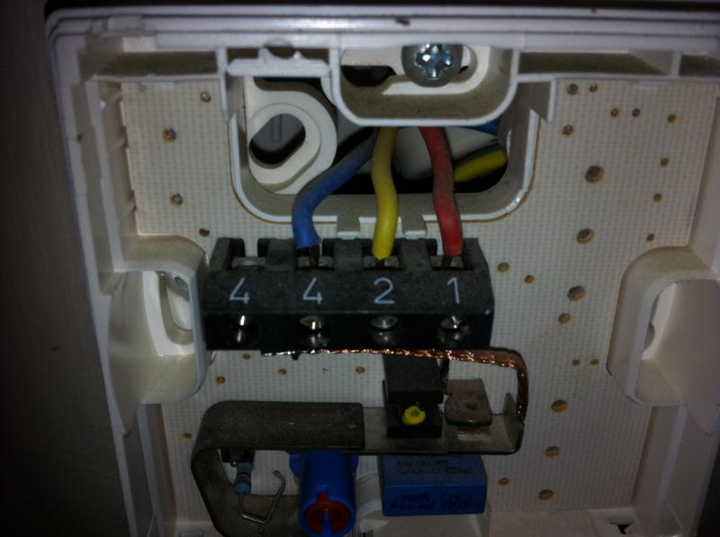
This is the old Potterton Thermostat wiring

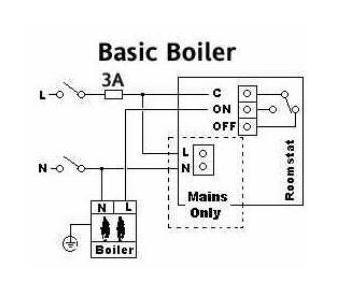
Wiring diagram for the new Drayton Digistat 22083

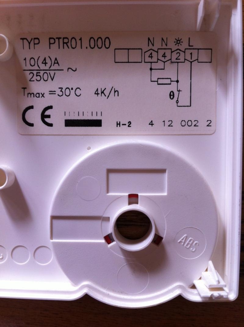
Wiring Diagram for the old Potterton Thermostat
 
Sponsored Links
For the battery powered version, you only need the 'live' and 'switched live' wires for the new stat as you say. The diagram you posted shows where they should be connected.

The 'permanent live' wire goes to the 'C' terminal

The 'switched live' wire goes to the 'On' terminal

As it's not mains powered, the neutral wire is not required anymore. This should be insulated using a small screw connector and tucked safely out of the way.

The question now, is which wire is which. Normally, the red wire is used for the permanent live, the yellow wire for the 'switched live' and the blue wire is neutral. However although the vast majority of installations use this format, it all depends upon the preferences of the person that wired it up in the first place. There are several ways to check.

1. By using a multimeter to test each wire
2. By looking at the other end of the cable to see where the wires are terminated
3. By finding a wiring diagram for the old Potterton thermostat and determining which terminal is which.

Looking at the photograph it appears to me that the red wire goes to the fixed contact, which in a mechanical heat only thermostat could be the permanent live, I can't see the other connections clearly enough to comment on them.
 
Thanks for the added photo. There you go then!

Red = Permanent live = 'C' terminal
Yellow = Switched live = 'On' terminal

Blue = Neutral = Isolate safely

As suspected but always best to be sure.
 
Sponsored Links
For the battery powered version, you only need the 'live' and 'switched live' wires for the new stat as you say. The diagram you posted shows where they should be connected.

The 'permanent live' wire goes to the 'C' terminal

The 'switched live' wire goes to the 'On' terminal

As it's not mains powered, the neutral wire is not required anymore. This should be insulated using a small screw connector and tucked safely out of the way.

The question now, is which wire is which. Normally, the red wire is used for the permanent live, the yellow wire for the 'switched live' and the blue wire is neutral. However although the vast majority of installations use this format, it all depends upon the preferences of the person that wired it up in the first place. There are several ways to check.

1. By using a multimeter to test each wire
2. By looking at the other end of the cable to see where the wires are terminated
3. By finding a wiring diagram for the old Potterton thermostat and determining which terminal is which.

Looking at the photograph it appears to me that the red wire goes to the fixed contact, which in a mechanical heat only thermostat could be the permanent live, I can't see the other connections clearly enough to comment on them.

Many thanks for your reply I found the Wiring Diagram on the back of the Old Potterton Thermostat and add its photo.
Think that the Red will go to the ON and the Yellow will go to C .. is that correct?
 

DIYnot Local

Staff member

If you need to find a tradesperson to get your job done, please try our local search below, or if you are doing it yourself you can find suppliers local to you.

Select the supplier or trade you require, enter your location to begin your search.


Are you a trade or supplier? You can create your listing free at DIYnot Local

 
Back
Top