I've recently moved in to a new (to me) property - circa early 80's build.
It has in the last 18 months had the hot and cold taps converted from gravity to sealed system The heating circuits have remained on gravity feed from the remaining small F&E tank in the loft.
The system has a lot of air being induced into it - which sounds like cavitation at the pump every couple of minutes when the system is running. It's not as severe when heating water only but more evident when rads are in use. The air is being captured at top of the magnetic filter assembly and two or 3 of the rads that seem most acute to it. Pump is set to level 1 to minimise the symptom and noise - it just worsens as pump flow is increased.
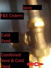
On looking at the pipework, I wonder if the feed and vent being joined above the pump flow could be responsible (circled in red in attached image)? Had a look at the feed tank and can see air bubbles being passed back up the feed pipe when the pump goes into air pushing mode and the end of the vent pipe is also very wet.
Layout seems to be boiler, pump, single pipe for feed (on left of the t in pic) vent (right of t) and then on to the motorised valves.

What's the general view, could the combined pipe being after the pump be a combination that'll be problem bound... or should I be looking elsewhere?
It has in the last 18 months had the hot and cold taps converted from gravity to sealed system The heating circuits have remained on gravity feed from the remaining small F&E tank in the loft.
The system has a lot of air being induced into it - which sounds like cavitation at the pump every couple of minutes when the system is running. It's not as severe when heating water only but more evident when rads are in use. The air is being captured at top of the magnetic filter assembly and two or 3 of the rads that seem most acute to it. Pump is set to level 1 to minimise the symptom and noise - it just worsens as pump flow is increased.
On looking at the pipework, I wonder if the feed and vent being joined above the pump flow could be responsible (circled in red in attached image)? Had a look at the feed tank and can see air bubbles being passed back up the feed pipe when the pump goes into air pushing mode and the end of the vent pipe is also very wet.
Layout seems to be boiler, pump, single pipe for feed (on left of the t in pic) vent (right of t) and then on to the motorised valves.
What's the general view, could the combined pipe being after the pump be a combination that'll be problem bound... or should I be looking elsewhere?