
You are using an out of date browser. It may not display this or other websites correctly.
You should upgrade or use an alternative browser.
You should upgrade or use an alternative browser.
Bathroom extractor fan isolation switch wiring
- Thread starter BobbyBrown
- Start date

It's up to you how you use L1 & L2 for permanent and switched live - either way round is fine.
Live? Not an accepted meaning of the term surely.It's up to you how you use L1 & L2 for permanent and switched live - either way round is fine.
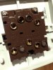
That is a carp terminal layout if ever I saw one.
That is a carp terminal layout if ever I saw one.
It sure is. So does the fan connect to the com terminals?
It depends on how the fan is wired.A simple question in case I make a horlicks of it. Bathroom extractor (timer) fitted with 3 core and earth. It'll go straight to the attached isolation switch. How is it wired from there please?
At the fan -
You have
Permanent Live
Switched Live and
Neutral.
PL probably brown.
The other two - depends
At the switch -
You have
L1 in L1 out
L2 in L2 out and
N in N out
Obviously you put the neutral in N
The other two don't really matter as long as ins and outs match.
I would put PL in L1 and SL in L2
Wires don't know what colour they are, it's the copper bit inside that complains if you mix them up.
Hi EFL,
with the switch in question though would the load (fan) go to the respective COM terminals?
with the switch in question though would the load (fan) go to the respective COM terminals?
There are no COMs on a fan isolator.
It looks like the body is also used for two-way switches so ignore the COMs.
Just three ins and outs (although in and out don't matter).
I have found another online like it and it is the right switch.
Just go by the L1, L2 and N markings - top and bottom.

It looks like the body is also used for two-way switches so ignore the COMs.
Just three ins and outs (although in and out don't matter).
I have found another online like it and it is the right switch.
Just go by the L1, L2 and N markings - top and bottom.
Thanks, will give it a try and report back
Do you actually know what that switch does?with the switch in question though would the load (fan) go to the respective COM terminals?
You have 3 load connections to make, and 3 supply.
Last edited:
Hi EFL,
Thanks for the help - all working correctly with no issues
Thanks for the help - all working correctly with no issues
DIYnot Local
Staff member
If you need to find a tradesperson to get your job done, please try our local search below, or if you are doing it yourself you can find suppliers local to you.
Select the supplier or trade you require, enter your location to begin your search.
Please select a service and enter a location to continue...
Are you a trade or supplier? You can create your listing free at DIYnot Local
Similar threads
- Replies
- 20
- Views
- 18K