CH Sytem vent pipe diameter

Joined
19 Oct 2008
Messages
112
Reaction score
2
Country
United Kingdom
In another post of mine we were trying to resolve a problem where air was briefly getting sucked into the primary whenever the pump started. Having verified the correct layout of pump, feed and vent many people have been scratching their heads trying to figure out why the air gets in (in addition, a quantity of water is ejected from the open vent whenever the pump stops).

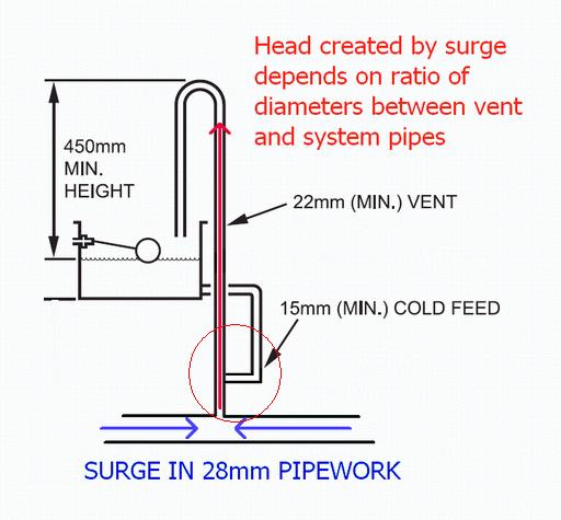
I now think I understand what the problem is, but I'm not finding any discussion about it and it's gone right over the heads of all the plumbers that have been called to invetigate. What is slightly unusual (but by no means unique) about my system is that it is mostly run in 28mm pipework. The vent pipe, however, is 22mm diameter all the way from the inlet of the pump up to the F/E tank a few meters above.

I'm no hydraulic engineer so I look to professionals for advice and information. Nowhere can I find recommendations about matching the diameters of these pipes, but what seems inevitable (and is actually happening) is that the velocity of the water moving between these components is amplified by the change in diameter. Why is water moving in the vent? Because (it seems to me) when the pump stops or starts, the flow can't instantly stop or start. That would be physically impossible.

From observation, a brief surge is created up the vent whenever the pump stops (I'm guessing there is a degree of rebound off the stationary pump?) and the difference between the diameters of the vent and main system pipework amplify the velocity of the water by a factor of 1.6 (the ratio of the two cross sectional areas of the pipes). This seems to have been enough to push a quantity of water up and out of the narrower vent pipe.

Also from observation (and symmetrically consistent) a quantity of water is momentarily sucked down from the head in the vent when the pump starts. With the narrower vent pipe, this quantity appears to be enough to allow air to be introduced with it as well.

So I'm left wondering why I can see no recommendation bout matching vent pipe diameter - although I have seen plenty of "fixes" involving combining vent and feed - and a "fix" involving the insertion of a wide section of vent etc. (mostly related to low head installations). I'm very curious to know what the professionals think about this which is why I have started this dedicated discussion topic :?:
 
Sponsored Links
So I'm left wondering why I can see no recommendation bout matching vent pipe diameter
Plenty of systems with serious circuit pipes only have smallish vent pipes.

COuld you do a representative sketch of the confiuration you have now? SHow distances etc.

The air in your system is one reason why it ejects water from the vent . When the pump starts the air is compressed, so when it stops the air springs back.

COmmon solution is to raise the height of the vent pipe so it accommodates more water:
(sketch took about a minute in Word, by the way)
ventraised.gif
 
OK ChrisR, here's how it's plumbed - as per boiler manual, except the pump is vertical and on the floor above the boiler. The system has been thoroughly checked to make sure it conforms to this layout - in particular the relationship between the vent, feed and pump...

systemlx0.gif


We raised the F/E tank recently and it made a big difference. It seems to have stopped air being drawn down when the pump starts, but it still ejects a little bit of water when the pump stops.

Before this we tried just raising the height of the vent but that made little difference. The higher head is clearly helping.

I understand what you say about air in the system creating a spring, but the system could be thoroughly bled, then stop/started a few times and instantly air would get in down the vent.

Seeing the velocity behind the water that was ejected, just raising the vent was obviously (in hindsight) not going to fix it. Increasing the capacity of the vent pipe however, would strike me as reducing the height of the surge/dip during pump start-up and shutdown. Like I say, it seems like basic hydraulics to me - velocity will go up when water is pushed from a larger to smaller diameter pipe.

In my other topic spacethegas provided this diagram which effectively implements what I'm talking about...

lowheadhv7.gif
 
SO, now I'm slowly catching up with the concept of SURGE. Apparently "surging" is the fancy plumbing term for the problem in my system.

Looking at the recommended installation diagram, the top of the open vent loop was shown at a minimum height of 450mm above the head in the F/E tank. This step is presumably to stop a surge getting up and over the top of the loop. The figure of 450mm is no doubt empirical.

But the height of the surge anticipated by these recommendations will be governed by a number of factors, and as I'm pointing out here, one very significant factor is the ratio of the diameters of the system and vent pipes. A surge in the system bore (28mm in my case) will be amplified when it enters the smaller 22mm vent pipe - by my calculation 1.6 times the velocity. Yet the best guide to this that I've seen is the note "22m (MIN.) VENT" on my boiler installation diagram posted above.

This should make it clearer:
system2zk3.gif


I feel like saying "come on guys" where's the acknowledgement of this apparently unrecognised issue? I've lost count of all the suggestions and red-herrings that have been thrown at this problem so far.
 
Sponsored Links
As a topical update to this thread I finally got round to replacing all the 22mm pipe in the vent T-off with 28mmm and the surging stopped. Some here may be surprised, some not. I wasn't - just very relieved (mostly of cash) .
 
Fine, but it would have been a quicker job to extend the whiite part of the pipe in my original answer in plastic, clipped up the rafters.
It's not tha ratio of the diameters which matters, it's whether you can accommodate the surge volume in the normally-empty part of the pipe.
So if you can't go up, you can go sideways.
Most systems don't surge that much.
 
Fogive if this has been mentioned before,but why not do away with separate feed and vents and replace both pipes with a 22mm cold feed(no valves at all).That config is permitted with a boiler that has overheat protection.Air being sucked in is then not possible from the expansion tank as the only open end is always below water level.
 
Fine, but it would have been a quicker job to extend the whiite part of the pipe in my original answer in plastic, clipped up the rafters.
It's not tha ratio of the diameters which matters, it's whether you can accommodate the surge volume in the normally-empty part of the pipe.
So if you can't go up, you can go sideways.
Most systems don't surge that much.

As I said above, that was tried before the F&E tank was raised but the plumber who did it was skeptical and didn't really "go for it" with the height. In hindsight, increasing the head by a metre or so damped the surge a bit and combined with the higher inverted U that was retained from the first experiment got the job ticked off for them.

As for the ratio it goes both ways. Sure it's a matter of accommodation, but the narrower the bore in the vent the higher any given surge will climb. Also the velocity multiplication factor was playing a large part in the water managing to get up and over the bend - hard to explain but what you could see coming out was more of a squirt than a pipe-bore full. Using pipework having the same CSA has calmed that completely.

Fogive if this has been mentioned before,but why not do away with separate feed and vents and replace both pipes with a 22mm cold feed(no valves at all).That config is permitted with a boiler that has overheat protection.Air being sucked in is then not possible from the expansion tank as the only open end is always below water level.

The very first attempt at a remedy was to do just that, but the transport of hot water into the F&E tank was significant - causing the plastic to go floppy (hence my complaint that it had become a hazard). I can see good reaons for having a 15mm feed and expansion in addition to a separate vent with a wider CSA. What's the reason for only permitting the combined feed and vent if the boiler has overheat protection?
 
In effect by combining the feed/vent to just one 22mm feed you are restricting the openness of the system and an overheat stat should shut the boiler down should the main stat not work.Just a further line of protection.Not allowed on older boilers with no overheat,although retro overheat kits are available for some boilers.
 
Fogive if this has been mentioned before,but why not do away with separate feed and vents and replace both pipes with a 22mm cold feed(no valves at all).That config is permitted with a boiler that has overheat protection.Air being sucked in is then not possible from the expansion tank as the only open end is always below water level.

Potential problems with combined feed and expansion pipes:

1. To avoid convection of hot water into the feed/ expansion tank, the U tube connection of the combined feed/ expansion pipe to the flow pipe from boiler is essential (as shown in your "low head installations figure). But with this line acting as vent pipe as well, it will not be able to bleed bubbles out of the system because they can't get around the U bend.

2. If you remove the U bend, bubbles can escape, but so can hot water (by natural convection) up the feed/ vent pipe into the feed tank. Only separate feed and vent pipes can remove this risk.

That's a pity because because combining the feed and vent pipes certainly reduces risk of air ingress. The better solution is as shown in your first diagram, with separate feed and vent pipes, feed pipe with U bend and vent pipe with surge vessel.

I too have suffered from the ignorance of installers over these issues. Why does their training not cover these fundamental principles?
 
Does anyone know where you can find one these surge expansion vessels as shown in the "Low Head Installation" diagram?
 
Why? The recommend route is to bring the cold feed below the 22mm pipe the come up to join the 22mm pipe. That way you don't get thermal cycling with hot water rising up the cold feed pipe.
 
I think I may have a handle on this and why joining the feed and vent helps.

Let's first get rid of what I don't think is happening

1. Pump expands the radiators/pipe when running (balloon effect). When pump turns off water goes back up to F&E tank, some up the overflow.

Gut call is not enough pressure from the pump, plus radiators/pipes too stiff to expand anything like enough to fill 300+mm of 22mm pipe.

2. Pump compresses trapped air when running. When pump turns off water goes back up to F&E tank, some up the overflow.

This seems more possible. If it is happening then should see a water drop in F&E tank when pump turns on. Need to check this with a boiler off so heating the water so it expands does confuse things. I don't think I've seen this in my case but may be happening to others.

And what I think is happening

3. Pump turns off, water stops, pressure rises behind pump because water doesn't want to stop. Likewise pressure falls in front of pump. Shockwave travels round system hits vent and cold feed. Vent is larger so pressure wave goes up this creating negative pressure behind it that sucks water down cold feed. This reverses, extra water height in vent pushes down and pushes water back into F&E tank. Water columns oscillate.

If the main rads/boiler heating loop has no air in it then the water flow into the vent pipe cannot be water from the main loop. For that to happen new water would need to flow into that loop since liquids don't compress/decompress. All that can happen in the main loop is a pressure shockwave. So that shockwave must be ringing the cold feed / vent U loop which is open to air and thus can be an oscillating U column of water. The test for this would be to run the pump (boiler off), perhaps with a higher speed, to get the overflowing condition. Then block the F&E tank outlet. With one part of the U column sealed it should not overflow

Note, that's just to prove the mechanism, blocking the F&E tank is not a fix. I have in mind a couple of fixes that might work.

a) a check valve directly across the pump blocking reverse flow but it will open when the pump turns off. Still get a shockwave though since you need a bit of pressure to move the check valve and a bit of time. Hopefully though it might reduce the shockwave.

b) A second link pipe between vent and cold feed, going downward to cold feed of course to stop thermal cycling (or perhaps a downward U loop in a horizontal pipe). Hopefully this would short circuit the oscillating column. Water would surge up the vent and then round this link pipe rather than overflowing into the F&E tank.
 

DIYnot Local

Staff member

If you need to find a tradesperson to get your job done, please try our local search below, or if you are doing it yourself you can find suppliers local to you.

Select the supplier or trade you require, enter your location to begin your search.


Are you a trade or supplier? You can create your listing free at DIYnot Local

 
Sponsored Links
Back
Top