change over switch wiring 240v

wub

Joined
24 Jun 2011
Messages
7
Reaction score
0
Country
United Kingdom
Hi can any body help, serched all over the web and cant find an answer. I have a Hymer 1990 motorhome recently bought. It has 240 hook up and a 240 genie. The previous ower f..ked about with the genie and wiring, made a god awfal mess, so i've taken it back to original, got the genie repaird, (faulty internal circuit board) and bought a change over relay from hymer, that they say was originally fitted to motorhomes with 240 hook uo and a genie.

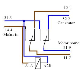
My understanding is you wire the 3 wire genie output to the change over switch and the 3 wire 240 hookup. The switch will automatically switch between hookup up and genie, not allowing 240 to travel back to genie or genie to try and charge the mains grid up!

My problem is trying to find out which terminals to connect the wires to as i also need a 3 wire off, to plumb into the motorhome 240v circuit. The Finder relay is 16A 250v 230v AC with 8 terminals A1 A,11 7,14 4,12 1, on one side and A2 B,31 9,34 6, 32 3,

This cost me £40

Does anybody have any knowledge of this?

And before anybody suggests a manual switch, i dont want this as my wife and kids use this camper on there own, and the start button for the genie is on the main consul, i dont want to worry about her forgetting or the kids fliping the genie start switch and there being an almightly bang as the genie gets fried!
 
Sponsored Links
There is a PDF on Finder relays here and it shows A1 A,11 7,14 4,12 1, on one side and A2 B,31 9,34 6, 32 3,
A1 A as one coil connection
A2 B as other coil connection
11 7 as common on one pole
31 9 as common on other pole
12 1 as normally closed from 11 7
14 4 as normally open from 11 7
32 2 as normally closed from 31 9
34 6 as normally open from 31 9
It is up to you to confirm these connections but if we assume this is connect then the first step is to decide which supply will be priority. If one assumes non generator as priority then the A1 A and A2 B will go to mains supply together with 14 4 and 34 6 which leaves 12 1 and 32 2 going to generator.
The home will be supplied from 11 7 and 31 9.
The relays will normally have a base and would not be wired direct and would be inside a suitable box which would require a key or tool entry.
At £40 I would have hoped it is a little more than just the relay and I wonder why no instructions. It did to be fair take some finding on the net from information given. But Google 62.32.8.240.0000 what I think likely part number of relay and I found the PDF. However it was a little guess work so up to you to confirm what I have found.
 
thanks ericmark

I was starting to loose faith. so does that mean assuming correc tly that mains is priority, that A1A A2B can be either mains live or neutral? And is that the case for the terminial, live or neutral? and i presume just join all the earths up together?

No it did'nt come with anything, and it has male spade connectors on the bottom, not ideal! and yes i'm going to put it in a large junction box.

thanks again
 
Ericmark could you help me a bit more please. I'm still not clear on this, i've looked up on the web and found the pdf's but its not clear to me. The way i'm seeing this is, A1A mains +, A2B mains -, what do you mean "together with 14 4 and 34 6"? Do you mean jump the cable to those as well, so mains + also to 14 4 and mains- also to 34 6?

Then 12 1 to genie +, 32 2 to genie -, 11 7 to supply to home +, 31 9 to supply home -. Is that right?

If i'm wrong can you spell it out in idiot form.

My part number is 62.82.8.230.0000, which is the same as the one you thought, but mine is flush mount with out a base.

Oh and i see i could have bought it for £9, not £40. Thats quite a mark up Hymer are making!

Thanks for you help
 
Sponsored Links
The way i'm seeing this is, A1A mains +, A2B mains -, what do you mean "together with 14 4 and 34 6"? Do you mean jump the cable to those as well,
Yes the A1A and A2B is the coil and that energises the relay and the 14 4 and 34 6 are normally open contacts.
I would have expected a base like shown click on picture for link. But I am unsure which is the right base for your relay.
Here is the relay RS Components as you say £8.91 plus vat and RS is expensive. Seems you have no alternative but use spade connectors. I would use fully insulated like this
736875_LB_00_FB.EPS.jpg
 
Hi really sorry to keep bothering you, but i still dont understand fully. I'm afraid my electriacl skills stop at basic stuff. I completly understand normal house stuff, and have done lots of work on the electrics my houses over the years, but relays confuse me!

So are you saying i dont connect 14 4 and 36 6? I'm sorry, I understand what relays do, but not how they work, so coil and energises are lost on me!

Probably best if you could just help me with what wires go where, either that or a whole lesson on relays.

Yes i would have prefered a base, but are going to use insulated spades as you suggest, which is apparently how they came out the factory new from Hymer.

Many thanks
 
This is basic wiring of relay. All earths just connect together and don't go through the relay. If I was doing the job I would have started with a consumer unit and used a din rail mounted relay so all the electrics were all in one place. Contactors like this
CMREL230SLASH20SLASH20.JPG
although not this one as it is not a change over but serves to show method will clip directly into a consumer unit and would have produced a professional looking job and also easy to maintain.

I think Hymer are German and this type of workmanship is typical. Where one can see it they are good but where it is not seen it seems they take the view well it works don't it! And yes it will work.

I would also want to add a fuse to the coil supply and of course there are issues with the positioning of RCD devices. But seems you don't have the option.

I frankly worry at directing some one who don't seem to grasp the working of the system as it is all too easy for something not to be as I think it is and so I could easy end up giving wrong advice.

At the end of the day you are responsible for what you are doing. I would advise you get some one with the required knowledge to check it all over.

To comply with 721.537.2.1.1 Each installation shall be provided with a main disconnector which shall disconnect all live conductors and which shall be suitably placed for ready operation within the caravan. In an installation consisting of only one final circuit, the isolating switch may be the overcurrent protective device fulfilling the requirements for isolation.

is going to be very hard where the device is not part of the consumer unit. In real terms to comply one would need a 4 pole isolator so both generator and mains are switched off with a single isolator within the motor home. But the German regulations are not as strict as ours they even have plugs which can be turned around and put in upside down.

So I would not think any British Electrician would pass the system you are installing.

edited to correct picture
 
Hi there is the original 4 pole isolator on the output side of the change over switch, ie between the relay and the rest of the motor home 240 volt sockets \ appliances.

Everything is there that was there from standard, except the change over switch, which am am trying to reinstall, as previous owner took it out (probably tried everything when the genie broke down or who knows? All i do know, was the genie circuit board was burnt out , and it cost me £350 to it fixed). Once this change over switch is fitted, everything is back to factory original, like any other hymer motorhome running around.

I have tested everything, the camper works fine on mains hookup, and when i rewire genie in, works fine on that as well. I just want to reinstall the change over switch for safty and ease of use reasons, not a 3 pin plug stuck on the end of the genie output 240v wire, which the previous owner fitted!!

I have tried 2 local electricains, who both looked bewilded when i explained what i wanted them to do!

I dont understand why this is getting so complicated, i am not rewiring anything, installing split charging etc, all i need to know is what wires to put on what terminals of the change over switch. I have 3 cables, genie in, poss neg and earth, mains in poss neg and earth and mains out.

I am very limited for space where all the wires converge so have to stick with what the manufactorer used, if i were to put a din rail type consumer unit in, i will have to start taking half the motor home apart to install longer cables etc. I think an isolater on the out put is suficent as when the mains is unplugged, its isolated and when the genie's off, its isolated.

I'm sorry Ban-all-shed, i dont agree, i have just installed a solar panal and controller. On the instructions it told me where to put the various wires, which i did as i am a compantant person to do this, but i dont know or need to know how the solar controller works inside? I understand why i need one and what it does, but not how it does it, which is a big difference.

I know what you are saying if i was a complete novice, trying to do this then i would try and persued them not to, but i am not a novice, i just need to know the connections, once i know this i can safly make the connections and its sorted.

I truly believe, in knowing your limitations and doing things (espeially electrical work) safely, but also believe in do it yourself, but in an intelligent and informed way and not relying on others to do everything for you.

Thanks for time, much appricated
 
I dont understand why this is getting so complicated,
Then you're not ready to DIY it.


all i need to know is what wires to put on what terminals of the change over switch.
Which you would be able to work out if you understood what to do.


I have 3 cables, genie in, poss neg and earth, mains in poss neg and earth and mains out.
No you don't. You have 3 cables, but not as you describe.


I'm sorry Ban-all-shed, i dont agree, i have just installed a solar panal and controller. On the instructions it told me where to put the various wires, which i did as i am a compantant person to do this, but i dont know or need to know how the solar controller works inside?
No you don't, but you do need to know exactly what it does with each input and to each output.


I understand why i need one and what it does, but not how it does it, which is a big difference.
And once you know what a changeover switch and/or changeover relay does with each input and to each output you'll be all set.


i am not a novice, i just need to know the connections,
Then work it out.


but also believe in do it yourself, but in an intelligent and informed way and not relying on others to do everything for you.
Which is what I'm saying.

Probably best if you could just help me with what wires go where,
That's relying on someone else to do the understanding how it works and what you're doing part of it all.
 
eric mark

In the diagram you sent, is that an energized view or not? As if its energized view, then the genie will never be able to close the circuit? in which case i'd need to put genie on to 12 1 and 32 2 normally closed, so that when i plug into the hook up mains, it energizes the switch and closes 14 4 and 34 6?

Does that make sence?

Nearly there!

Thanks
 
Yes you spotted my deliberate mistake of the day!!!!

Which is the point. All too easy to make a mistake. Now corrected.

There are four levels of skill
1) Ordinary person
2) Instructed person
3) Skilled person
4) Competent person

You claim to be highest level "Competent" but want us to tell you how to do it!

As I have said Hymer are German and as such will maybe comply with German laws. I realise to change to the higher British regulations may not be possible but that leaves a problem with paperwork in getting a periodic inspection report or Electrical Installation Condition Report as it is now called. Some sites are now requiring these for older units and want you need is the comment "Satisfactory" there is no Pass and Fail.

As done by the previous owner with simple plugs likely it would have been "Satisfactory" and for me not to tell you there may be a problem is to my mind wrong.

To make out the report the Electrician has to satisfy some one to insure him for Professional Indemnity which is higher than normal PLI insurance and of course he needs to be careful not to miss anything which could result in a claim. Normally he will need to hold a C&G 2391 which is no easy exam with many electricians failing.

I think BAS is correct you don't have the skill required but I think you will go ahead anyway so may as well get you to do it as well as possible.
 
Thanks for your help, its all working perfectly now, and after years of not bothering to sit down and work out how a relay works, i now understand, and actually as the change over relay i had was in a transparent case, when i actually looked, you could work it out your self.

Its just one of those things, when you hear these expressions, coil, normally closed, normally open, energized and you dont no what they refer to, like, in part of my work with pc's jpeg, SBS, host client etc, it just needs someone to tell you, for instance i now understand that "normally closed" means, the contacts are closed unless the relay is energized, which activates the coil, which opens the contacts or vice versa.

You never stop learning.

Thanks again, now have a safe change over switch, not a live 3 pin plug!
 
as the change over relay i had was in a transparent case, when i actually looked, you could work it out your self.
Indeed - and it was because you appeared unable or unwilling to do that that I was concerned about your basic competence. Even if it hadn't had a transparent case you could have worked it out using a multimeter or continuity tester.


Its just one of those things, when you hear these expressions, coil, normally closed, normally open, energized and you dont no what they refer to, like, in part of my work with pc's jpeg, SBS, host client etc, it just needs someone to tell you,
Which was why I referred you to the Wikipedia article.


You never stop learning.
Only when you're dead. (Cause and Effect can be either way round.)
 

DIYnot Local

Staff member

If you need to find a tradesperson to get your job done, please try our local search below, or if you are doing it yourself you can find suppliers local to you.

Select the supplier or trade you require, enter your location to begin your search.


Are you a trade or supplier? You can create your listing free at DIYnot Local

 
Sponsored Links
Back
Top