Extending feed from outdoor socket to remote control device

Joined
20 Sep 2009
Messages
37
Reaction score
1
Location
Leeds
Country
United Kingdom
Hi there,

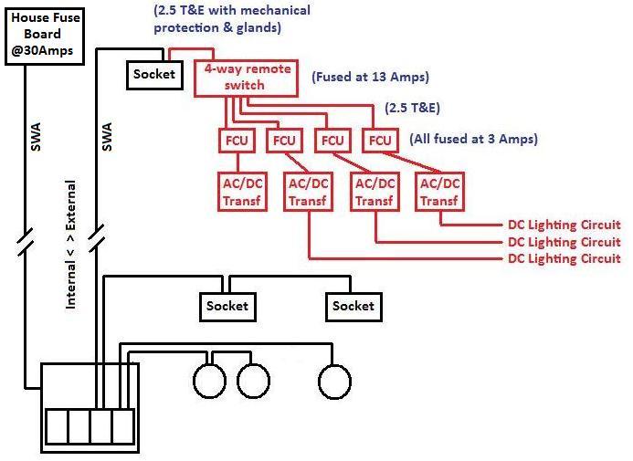
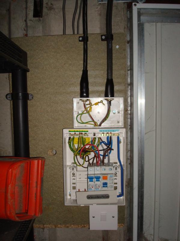
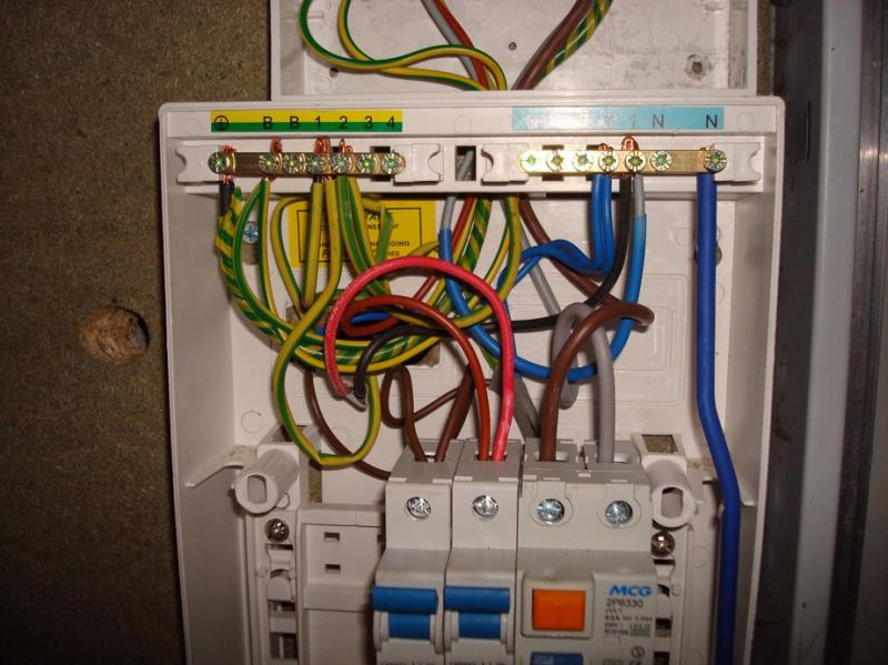
I recently had my garage reconnected to the house fuse board by a spark. This is on a dedicated 30A circuit using SWA. The garage now has a four way RCD protected board. From there, one circuit is for the garage lights, and another circuit provides the feed for the sockets inside the garage along with a thinner stretch of SWA that connects to an external single socket on the house exterior.

From that external socket, I wish to power the following device:

http://www.maplin.co.uk/4-way-remote-controlled-outdoor-switch-box-510558

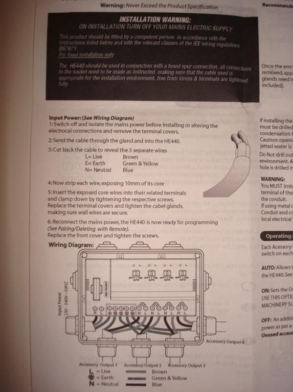
The device is fused at 13A, with an input power of 230-240V ~ 50HZ. Output is the same with a total combined load of 3000W. The four feeds that come from this switchbox will eventually be four transformers that feed separate low voltage lighting DC circuits. The transformers will be housed in a second IP-rated enclosure.

The socket, switch box and box housing the transformers will all be next to eachother.

Questions:

1. Assuming I get a spark out to connect this up, will it merely be a case of taking a short feed in conduit and glands from the socket to the switch box?

2. Assuming the switch box is now powered, do each of the four feeds to the transformers need to be individually fused? The instructions are less than clear on the requirements.

Thanks,
W
 
Sponsored Links
The first thing to check would be the configuration of your socket circuit is it a small ring final circuit or a radial circuit, this could whether you can take a direct feed from the external socket outlet as it could be a spurred socket of a ring final which means some alteration may be need as to the addition of a Fused Connection Unit prior to this socket.
But if it is on a continuous ring or the end of a radial, I can't see any reason way it can not be directly fitted, the cable will still need mechanical protection, a bit of T&E in plastic conduit at ground level, could be easily damaged.
 
I though you might say something like that. :D

I'll have to check the circuit layout with regards to the internal garage sockets, but I'm almost certain the SWA goes direct to the garage board.

Let me get back to you (and thanks for dipping in with your reply).

W
 
re
do each of the four feeds to the transformers need to be individually fused?
You would need to check with Maplin but with similar products (eg Blagdon) each of the switched outputs have their own fuse inside the box.
 
Sponsored Links
Hi there,

Sorry for the delay in getting back to you. Managed to take a look at the garage circuitry which is attached in the diagram.

What I don't know is exactly how (or where) the SWA to the external socket is joined with the 2.5 T&E internal garage circuit. I only know that they run off the same breaker, and I'm reluctant to go poking around or taking the board off the wall unless necessary.

The red sections represent my proposed extension to the circuit.

re
do each of the four feeds to the transformers need to be individually fused?
You would need to check with Maplin but with similar products (eg Blagdon) each of the switched outputs have their own fuse inside the box.
That's what I had assumed when I bought the product, however, looking at the instructions, it seems to indicate that there is merely a single fuse (at 13A) which I assume is there to protect the switching device, rather than any connected accessories.


The instructions suggest that the device should be used in conjunction with a fused spur connection (see black box in picture), but does not indicate anything more than that.

I am therefore assuming that each connected accessory (in this case AC/DC transformers) should be protected with an FCU rated to the accessory's requirements. All of that would be protected in the same IP-rated enclosure. Each DC circuit will not exceed 150w if using traditional lamps, 50w if using LEDs.

Is what I'm proposing correct (although I suspect I might be panned for the mechanical protection)?

Any help appreciated.

Thanks,
W
 
I would assume the SWA is connected via one of the socket outlets in the garage. If you power down the circuit, you could investigate within the outlets.
 
I would assume the SWA is connected via one of the socket outlets in the garage. If you power down the circuit, you could investigate within the outlets.
Nope, just powered down the whole house and took the breaker box apart.

SWA to external socket is connected to the same terminal in the breaker box as the garage sockets circuit. Pictures should explain.


SWA on left of shot is to external socket. SWA on right of shot is from house fuse box.

Sockets circuit is the right-hand breaker. Lighting circuit is left-hand breaker. Oh, there's actually two 1.5 T&E that feed different lights. One feeds the internal fluorescent strips, and the other a low-wattage security light (so my diagram was wrong on the lighting circuit (amended the diagram to be correct)).
 
Tentative *bump* :D

Based on the socket circuit diagram I've provided, will it merely be a case of taking a short feed in conduit and glands from the socket to the switch box?

Thanks,
W
 
So fit a 16A mcb in the third slot in the breaker box (essentially giving a dedicated external circuit) and keep the internal sockets on the existing mcb?
 

DIYnot Local

Staff member

If you need to find a tradesperson to get your job done, please try our local search below, or if you are doing it yourself you can find suppliers local to you.

Select the supplier or trade you require, enter your location to begin your search.


Are you a trade or supplier? You can create your listing free at DIYnot Local

 
Sponsored Links
Back
Top