Halstead EDEN CBX 32 boiler : No hot water and lock-out

Joined
21 Feb 2009
Messages
174
Reaction score
0
Location
Cleveland
Country
United Kingdom
We’ve had this boiler for 4 years and it’s been ok, but it now has developed 2 problems.

1. There is no hot water at all.

2. When the central heating is on, it fires up and runs for about 2 minutes then locks out. If you leave it alone for about 10 minutes it eventually fires up again and does exactly the same thing again.


Solutions I've tried so far.

1. I've removed the plate heat exchanger and filter and cleaned them out. There was hardly any sludge in there to be honest.

2. I’ve changed the hot water flow turbine for a new one, but there is still no hot water. Even if I put the boiler in comfort mode it never fires up. In comfort mode the boiler should fire up occasionally, so there is a bit of immediate hot water, it doesn't do this anymore in comfort mode.

3. I've read on here (and other forums) that the something called the diverter valve motor can fail on these boilers. However by using a small mirror, I can see the diverter valve moving when the central heating is switched on. However when I turn on the hot water, it doesn't move back to the hot water position (It was actually this that lead me to think that the flow turbine was faulty.) However if you turn the central heating off and hot water off and wait for a few minutes the diverter valve moves back to the hot water position itself. This suggests to me the diverter valve is probably working ok.

Has anyone got any other ideas of what could cause these 2 faults? I am wondering if the new flow turbine I've bought could also be faulty, but my gut feeling is telling both are ok. Is there any way of testing them with a multimeter so I can confirm they are both faulty or not?

But regardless of whether the flow turbines are faulty or not, it doesn't explain why the boiler doesn't fire up occasionally in comfort mode (for that bit of instant hot water).

Thanks in advance
 
Sponsored Links
Sounds like a faulty PCB.

The flow turbine can be checked but needs considerable understanding of electronics.

I thin k that the plate HE is located within the sealed cover which we don't advise DIYers to open.

Tony
 
Sounds like a faulty PCB.

Thanks very much for replying.

Yes, that seems like the only logical explanation.

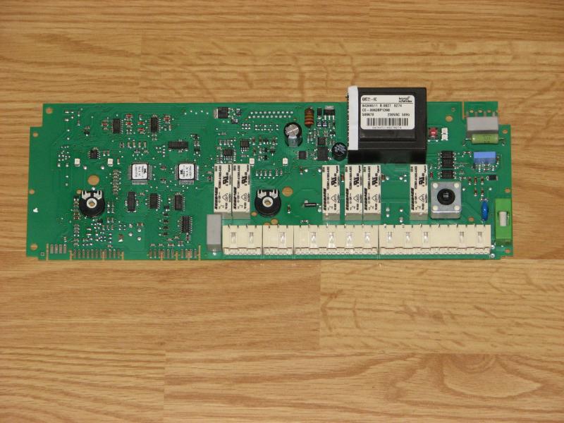
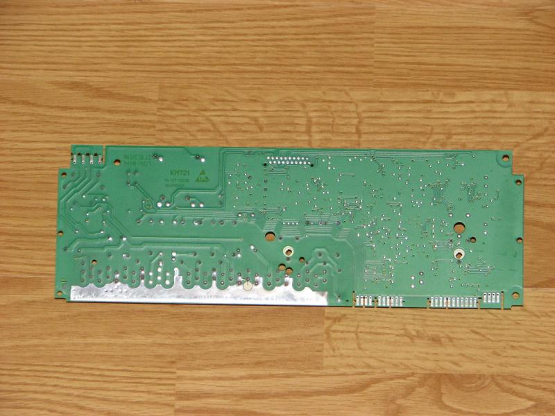
I've took the PCB out and had a good look (and sniff) of it. Nothing obvious seems to be wrong with it, I can't see anything burnt out or any dry joints or any broken tracks. It's dual layered board with lots of surface mounted components on it. I've even had a very close look at it with a set of eye loops, I can't see anything broken or burnt with those either.

Here is a picture of both sides of it.


The cheapest brand new one I've found costs £122+VAT. But I've found a couple of companies on the internet offering a PCB exchange service for about £75. So I will probably try one of those.

If anyone has any other ideas, please feel free to wade in.

Thanks in advance.
 
Well after a long wait. The PCB has now been changed (bought a second hand one), but I still have the same major problem which is no hot water.

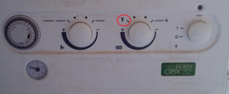
I have however, managed to fix the central heating problem. If I put the boiler into “service function" mode by turning the radiator temperature knob to the spanner position.


After a couple of minutes the LEDS would flash this sequence.

So I removed the flow and return temperature sensors and the flue sensor. And I tested them all using my multimeter. The flow and return sensors were both fine, but I noticed that the flue sensor sometimes measured infinite resistance. So I bought a new one and the central heating is now working perfectly.

Anyway, back to the no hot water problem.

So far I've changed the hot water flow turbine and the PCB. Surely I can't have 2 PCBs with the same fault or 2 faulty flow turbines?

To rule out the flow turbines being faulty, does anybody know how I can test them? I’ve got a multimeter. And if it involves building a circuit of some kind, I’ve also got a piece of breadboard, some diodes, LEDS, resistors and capacitors etc etc. Any electronics whizz kidz on here?
 
Sponsored Links
But regardless of whether the flow turbines are faulty or not, it doesn't explain why the boiler doesn't fire up occasionally in comfort mode (for that bit of instant hot water).

Oh but it does, it tells a lot really
the boiler isn't firing occasionally in comfort mode because comfort mode is automatically suspended after long periods of no hot water demand
therefore it tells you the boiler hasn't detected a DHW demand in a while which again points to the flow turbine.
you have already changed the turbine so check the integrity of the wiring between the turbine and plug x8
also check the dhw filter (its in between the cold inlet and the turbine)

Matt
Thanks for replying. I totally understand what you're saying regarding why the comfort mode setting is not firing up the boiler.

I have checked, re-checked and triple checked the wiring from the flow turbine connector to the pcb connector with my multimeter and all 3 wires are working fine. The dhw filter is also clean as a whistle and the flow from the hot tap (even though it's cold) is very good, so it's definitely not a low water pressure problem (in fact the water pressure is no different from when the hot water used to work).

I must have 2 faulty flow turbines or 2 PCB's with the same problem, it's the only logical explanation. There is nothing else to test. Is there?

Is there any way of testing these flow turbines? Maybe building a circuit that makes an LED go brighter the more you crank open the hot tap? On what electrical principle do they work? Is there a pinout explaining what the 3 pins are for?

I've found this on the manufactures website, but it's not giving much information away.

http://www.caleffi.nl/caleffi/en_NL...catalog~serie.jsp/posizione/disegni/index.sdo
 
Basically these have a turbine with a magnet embedded in the rotor.

The early ones had a pickup coil to sense the rotating magnetic field. Of course they only had two wires!

The later ones used a Hall effect sensor incorporating a Schmitt trigger so that they give a square wave output.

You will find that two of the wires are the supply, usually 5v DC which you should be able to measure and often red and black.

The other, usually in the middle is the detector output. This should switch from about 1v to 4v as the turbine is rotated.

When water is flowing the turbine will rotate fast and produce a square wave which can be viewed on a scope or measured as an AC voltage or have the frequency measured.

In your case you need to confirm that the detector is in fact giving the correct output signal.

They will usually operate with the water flow in either direction but you cannot assume that. Presumably you are confident the DHW flow is in the correct direction?

Tony
 
They will usually operate with the water flow in either direction but you cannot assume that. Presumably you are confident the DHW flow is in the correct direction?

Yep I was going to mention this too, and also the link you posted shows that particular item as a switch not a turbine and it also shows it as a unidirectional device btw

take the plug off the turbine and check for between 5 and 12ish vdc on two of the pins
but before you do that just to echo Tony, check that it is installed the correct way round

Matt
 
Thanks for the replies.

They will usually operate with the water flow in either direction but you cannot assume that. Presumably you are confident the DHW flow is in the correct direction?

I'm 100% sure that I've got the turbine connected the correct way around, I've checked that many times. It was worth asking the question though, because it could well be something utterly daft going on here.

Basically these have a turbine with a magnet embedded in the rotor.

The early ones had a pickup coil to sense the rotating magnetic field. Of course they only had two wires!

The later ones used a Hall effect sensor incorporating a Schmitt trigger so that they give a square wave output.

You will find that two of the wires are the supply, usually 5v DC which you should be able to measure and often red and black.

The other, usually in the middle is the detector output. This should switch from about 1v to 4v as the turbine is rotated.

The plug that goes into the flow turbine has 3 wires on it, they are Brown, Green and Red (Green is in the middle). So I'm guessing that Brown should be ground (0v), green should be the trigger and red +5v (or +12v)? How do you know if it should be +5v or +12v, is there a special Halstead manual that tells you this information for definite or do you guys just know this from experience?

take the plug off the turbine and check for between 5 and 12ish vdc on two of the pins

Matt

I've done that. I measured a steady -1.12v across the red and brown wires (to repeat minus 1.12v). The brown wire was definitely connected to the black lead on my multimeter and the red was definitely connected to red lead on my multimeter, my multimeter was also definitely set to DC volts. That reading doesn't seem right, does it? Did I chose the wrong 2 wires or should I be measuring between each wire and the metal case of the boiler? Am I right or wrong about the Brown wire being connected to ground?

Thanks
 
Simple answer is I don't know!

Try measuring EACH wire to the chassis of the boiler.

One will probably be zero volts.

Expect to find the two supply wires with perhaps +5 or +12 v and the other will be the output.

Tony
 
I've done that. I measured a steady -1.12v across the red and brown wires (to repeat minus 1.12v). The brown wire was definitely connected to the black lead on my multimeter and the red was definitely connected to red lead on my multimeter, my multimeter was also definitely set to DC volts. That reading doesn't seem right, does it? Did I chose the wrong 2 wires or should I be measuring between each wire and the metal case of the boiler? Am I right or wrong about the Brown wire being connected to ground?

Thanks
there isn't enough supply voltage
try all combinations there are only three to do
ignoring the polarity, there should definitely be a reading of between 5 and 12vdc between 2 of them

Matt
 
I've managed to measure the voltages between the wires.

Here are the results

Brown(+) Red(-) +1.12v
Brown(+) Green(-) +4.96v
Red(+) Green(-) +3.84v

(+) means connected to the positive lead of my multimeter
(-) means connected to the negative lead of my multimeter

Do these readings make sense?

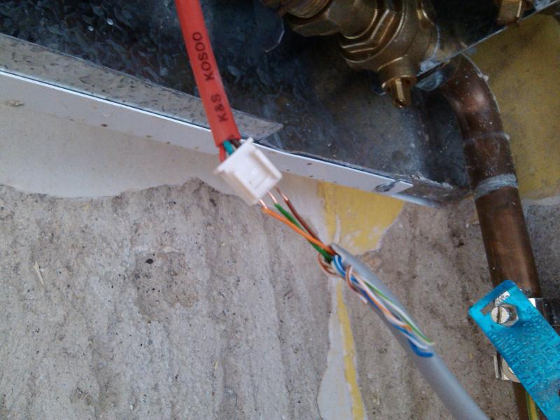
To get the readings, I used 3 strands of solid core cat 5 network cable. It fitted nicely into the holes on the turbine plug. Here is a picture.


I tried taking reading between the boilers case and each wire but all I got was a few fluctuating minivolts (noise?). I guess it's because the case of the boiler is connected to mains earth and not the ground rail of the PCB?
 
OK

The Green is chassis.

The brown is the +5v supply.

The red is the signal out which at the time of measurement was in the high state.

Rotate the turbine and the red will cycle between about =1v and +4v.

Tony
 
OK

The Green is chassis.

The brown is the +5v supply.

The red is the signal out which at the time of measurement was in the high state.

Rotate the turbine and the red will cycle between about =1v and +4v.

Tony

Thanks Agile. I totally understand what you're saying. However when I took those voltage measurements I didn't have a turbine connected (I couldn't think of a way of doing it, without having a second 3 pin plug to go into the 3 pin socket on the turbine).

So the red wire must default to the high state (+4v).

The measurements do prove that there is power on the turbine lead though. So I am going to buy another turbine. Fingers crossed it will work. I will report back with the results.
 
You should always test turbines etc. with the unit connected!

The receiving circuit must be providing that voltage.

I thought you had already replaced the turbine.

I would be measuring with the Turbo connected and rotate the rotor to see the output voltage cycle!

Tony
 

DIYnot Local

Staff member

If you need to find a tradesperson to get your job done, please try our local search below, or if you are doing it yourself you can find suppliers local to you.

Select the supplier or trade you require, enter your location to begin your search.


Are you a trade or supplier? You can create your listing free at DIYnot Local

 
Sponsored Links
Back
Top