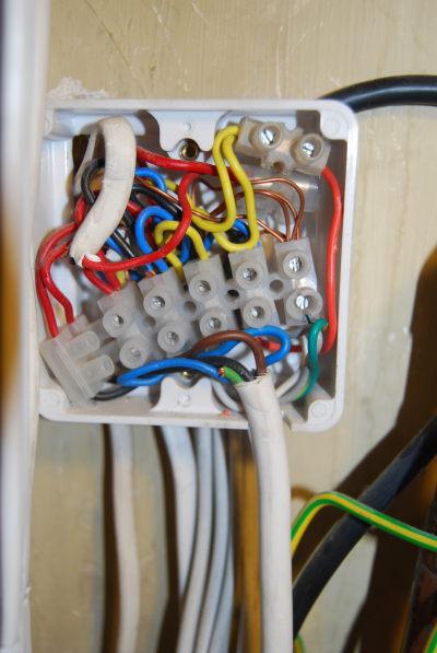
Hi, I would be grateful for some thoughts on this issue in my CH system.
The problem:
I can only get the heating to work (boiler firing up and rads heating) if the programmer is also set to have the hot water on (not necessarily calling for heat - just on). This was the situation when I moved in here 6 months ago so I don't know if it's always been like that or a fault that has developed previously - I suspect that the system is probably 12 - 15 years old.
The system appears to be a Sundial Y plan - I have a Honeywell V4073a mid-position valve, and what appears to be a Honeywell ST699 programmer, plus the usual tank and room stats.
I am trying to determine if the problem is with the valve, the programmer, or both.
I've checked the very useful website on what should happen in a Y-plan system, http://octaveblue.co.uk/c_heating/index.htm
I've also attempted to understand how the valve itself works, http://www.diyfaq.org.uk/plumbing/controls/midpositionvalve.htm, but probably don't fully understand the exact sequence of operations!
I've also checked Honeywell's own FAQ on the valve: http://www.honeywelluk.com/documents/All/pdf/975.pdf
I've measured the voltages between neutral and each of the white, grey and orange connections to the valve, and will summarise these below for various programmer combinations (absolute values are probably subject to some error as it's just a cheap multimeter):
1) HW off, CH on and calling for heat: Programmer CH LED comes on and relay clicks, but no movement from valve and boiler doesn't fire up
White: 248v, Grey: 63v, Orange: 128v
2) HW on but not calling for heat, CH on and calling for heat:
Valve moves, boiler fires up, heating works normally
White: 245v, Grey: 248v, Orange: 248v
3) HW on, calling; CH on, calling:
Valve moves again, presumably to mid-position as both CH and HW work as expected
White: 248v, Grey: 66v, Orange: 248v
OK, that's the facts of the matter. As for trying to work out what's at fault -
In scenario 1) My understanding is that the voltage I'm measuring on the grey wire is the output from the programmer 'HW OFF' connection. it is 63v when it should be live. Grey and white are the control inputs to the valve. In this situation Orange should also be live (to fire the boiler) but it's 128v.
In scenario 2), when I turn the programmer so that as well as CH on and calling, HW is also on (but not calling for heat) then grey, white and orange are all live as expected, and everything works as expected.
My presumption is that there is a fault in the programmer - possibly a sticky relay feeding the HW-OFF output, or something else that's failed.
I can't see how I should ever get a voltage of 66/63v on the grey wire.
However, I am wondering if the valve powerhead itself is also faulty since I can't see how in scenario 1) I should get an output of 128v on the orange connection; according to the details of operation of the valve, in this scenario, both white and grey should be live, and this will connect the orange output to live via the internal SW2 of the valve. However in my case, grey ISN'T live but 63v so maybe the internal operation of the valve is affected - but I still can't understand orange being 128v not 0 or 245!
OK. Sorry for the long (but hopefully logical) post.
Although I need a plumber for some additional work, changing the powerhead or the programmer is something I can do myself. They are of course both expensive components, so I would very much welcome any thoughts or opinions as to which is at fault - or most likely to be. My money is still with the programmer at least - maybe the powerhead too.
I may have missed some diagnostic steps but can check other things too if anyone thinks it's worthwhile.
Thanks in advance ....
Phil
 )
)