Heating Problem - Potterton Boiler - Micro Bore System

The pump was installed with the flow arrows pointing up, the flow comes in at the bottom and goes out at top onto the CH and HW motorised valves. You can see from the photograph the Grundfos label is the correct way up.

The label can be rotated to any orientation that you choose!

Most would have advised using a 15-60 pump on a microbore system.

Tony


As stated in the quote the arrows (cast in the body of the pump) were pointing up, to me this means the direction of flow is up and the also meant the label was in the correct orientation. The rotaion of the pump was checked and was found to be in the correct direction according to Grundfos.

With the flow coming in at the bottom and going out at the top (arrows pointing UP), the flow from the boiler into the system would be the correct direction.

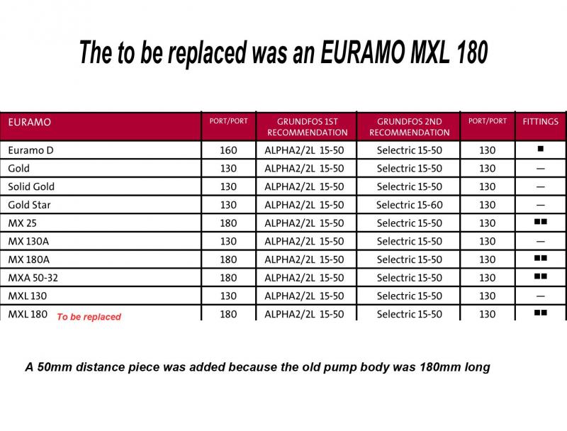
The 15-50 pump was the direct replacement recommended by Grundfos and was confirmed by the local pump supplier.

Please see selection chart picture for more information.


Sponsored Links
Yesterday, I fitted a Primaflow 3/8” Air Eliminator (automatic bleed valve).


Completely drained the system, flushed with fresh water and refilled.

Pumped the system without the boiler switched on.

Bled each radiator in turn, starting at the bottom radiator.

Then opened the red cap on the automatic bleed valve and a very large volume of air came out. (red cap must now remain open)

Then bled each radiator again in turn, starting at the bottom radiator.

Then operated the circulating pump and open and closed the motorised valves manually and forced air out of the automatic bleed valve on several occasions.

Then started the boiler.

The whole system came up to temperature and appears to be operating correctly now.

For the first time in two years the CH was able to establish a room temperature in the lounge of 22degC with -2degC outside.

The HW water temperature has been reduced back to 60degC.

The CH now works without having the HW switched on.

Conclusion:

There must have been an airlock is the microbore manifold system that was restricting the flow of CH water to the boiler and when the HW was switched on the water flow was sufficient to allow the CH to operate albeit not correctly.

It was possible the airlock only became a problem once the CH water became hot and trapped air expanded and therefore restricted the return CH water flow.

:D :D
 
That is good news.
I agree, with the HW circulating there was enough suction on the return to the boiler to create some movement in the air lock, but not enough to expel it.
It is very rewarding when you get success from your efforts!
 
Sponsored Links
That is good news.
I agree, with the HW circulating there was enough suction on the return to the boiler to create some movement in the air lock, but not enough to expel it.
It is very rewarding when you get success from your efforts!

Thank you for valued support and interest.

Alan :D :D :D
 

DIYnot Local

Staff member

If you need to find a tradesperson to get your job done, please try our local search below, or if you are doing it yourself you can find suppliers local to you.

Select the supplier or trade you require, enter your location to begin your search.


Are you a trade or supplier? You can create your listing free at DIYnot Local

 
Back
Top