Heating zone issue

Joined
28 Mar 2021
Messages
10
Reaction score
0
Country
United Kingdom
Hi, I am looking for advise on a zoneing issue on heating system.

I last year migrated to heatmiser uh4 wiring center, I believed I did the wiring correct and lived with it for a year. But this time being cautious about the utility bills I have been monitoring my usage. But I found an which went unnoticed in this one year.
I have 2 zones, one for all the radiators and one for the UFH. These 2 zones are isolated by 2 honewell 2 port motorised valves. I can turn on each zones individually and turn it off individually however the problem is that when both are on and you want to turn one off, it doesn't turn off. So I have to go ahead and turn both of them and then turn on the one that i want to stay on. Manually i could manage, but I am using hive and it is on schedule, so even if the schedule for one is set to be off, the thermostat says off, but the value is still open and water is still moving in that zone.

So I spent one full day re-thinking and tweaking the wiring but no joy. However, I have found what is causing this.
And it is something to do with wiring.
To explain the wiring. The thermostat wiring is no issue, it is the honeywell valve wiring that is an issue.
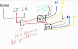
The boiler has 5 wires, brown n black going into line, green into earth, blue into neutral and then there is the grey that is connected to orange cables of the 2 morotised valves which in return go into the LS of the boiler trigger port on the heatmiser UH4.
The valve cables are place as such. Brown to line, blue neutral, grean earth and then grey to line as well. To reiterated bothe valves work, on and off individually but when both are on you cannot turn off one. I could feel it is because of 2 oranges connected the boiler trigger grey cable. So when the heating is turned on, the grey cable from the valve which connected to live triggers current to orange and then that triggers the boiler, but when the both valves (thermostats) are turned on and one is truned off the circuit doesnt break as the orange cable of the turned off valve carrys the current and pushes it back to the grey hence completing the circuit and keeping it on.
Hence looking for advise as to what can I do fix this and stop this reverse electricity.

Please advise.
 
Sponsored Links
Sounds like you've hit the standard trap- using the switched live from the thermostats to both drive the valve and feed the microswitch and latching both until both are satisfied.
Assuming your control circuits are 240v,
All neutrals got to neutral
All earths go to earth.
Permanent Live goes into controller
Permanent Live goes to the orange wires on the motorised valves.
Switched live goes from controller to thermostat.
Switched switched live goes from thermostat to live on relevant motorised valve.
Hi, Thanks for your reply, but sorry I do not understand few bits here. When you say "Switched live goes from controller to thermostat" by controller do you mean the boiler enable cable? I thought, it goes to LR port on the heatmiser UH4. And also I have 2 thermostats, one for each valve.

"Permanent Live goes to the orange wires on the motorised valves" I understand, the orange wire gets live feed from the grey wire of teh valve when it turns on and then triggers the bolier. I have attached a diagram to highlight were I feel is the problem and the current reverseses there.
 

Attachments

  • SmartSelect_20221118_152835_Samsung Notes.jpg
    SmartSelect_20221118_152835_Samsung Notes.jpg
    122.5 KB · Views: 53
I am having trouble following the wiring descriptions.


See diagram:

N.B. the Greys are Permanent Live and are connected.

The Browns are not connected and operate their particular valve motor when live - calling for heat.

the Oranges are connected and switch on the boiler when either motor operates its valve switch.

1668790081715.png


Obviously the Blue Neutrals are connected as are the Green Earths.
 
Sponsored Links
I am having trouble following the wiring descriptions.


See diagram:

N.B. the Greys are Permanent Live and are connected.

The Browns are not connected and operate their particular valve motor when live - calling for heat.

the Oranges are connected and switch on the boiler when either motor operates its valve switch.

View attachment 286020

Obviously the Blue Neutrals are connected as are the Green Earths.
Thanks, this is making sense and I get a feeling this is exactly how i have it connected. But what do you mean by a controller? And the orange cable is connect to the boiler enabler at port 10, which is the LS port in the heatmiser UH4 wiring centre, how would the same above diagram look like in the heatmiser? I hav attached the heatmiser manual here for reference. My UHF is in zone one and the radiators are in zone 4. Attached photo of the wiring centre. the white cable at the bottom is the boiler cable.
 

Attachments

  • UH4-Manual.pdf
    625.5 KB · Views: 80
  • 16687923219658138453054566121098.jpg
    16687923219658138453054566121098.jpg
    286.9 KB · Views: 82
I made same error, with flat and house, needed to add two relays, if one pump would have worked, but one boiler with two pumps, still not A1 as only one relay fitted, but hardly use flat.
 
I cannot think of any wiring mistake which would lead to the symptoms you state.

Only being able to have both valves working together at any time - yes - but only sometimes - no.


Let's see if we can summon @stem.
 
This is the common mistake which creates the problem
1668814044403.png


In fact it's often compounded by the supply coming from 2 different sources ie heating & hot water circuits from timeswitch.
If both valves are open and one output of the timeswitch is switched off, not only will its valve remain open but the neon will remain lit.
1668814616309.png


I once had a similar issue with 2 boilers running into a common flue fan and the second boiler would remain enabled. But of course the staff didn't understand the actual issue and it took several visits to get to the bottom of. When one is dealing with large boilers it can be a heck of a lot of wasted gas and potentially a lot of hazard/risk.
 
Last edited:
Thanks, this is making sense and I get a feeling this is exactly how i have it connected. But what do you mean by a controller? And the orange cable is connect to the boiler enabler at port 10, which is the LS port in the heatmiser UH4 wiring centre, how would the same above diagram look like in the heatmiser? I hav attached the heatmiser manual here for reference. My UHF is in zone one and the radiators are in zone 4. Attached photo of the wiring centre. the white cable at the bottom is the boiler cable.
What a mess.
Are your thermostats programmable (as in do you set on/off times and different setpoints on them)? If yes then you have combined thermostat/programmers.
That wiring centre is a bit poor since it only seems to cater for one valve with switch- in fact I would suggest that it's overcomplicated and is just confusing matters.
Do you have a separate pump with manifold, blending valve etc on the UFH or is it all on the 1 pump?

EDIT
Sketch a schematic (pencil or pen and paper is fine, just take a pic of it when you're done) of what you have got (boiler, pump, thermostats, motorised valves, UFH actuators) and what is connected to what. No need to draw all the neutrals and earths- an N and E at each device will do
 
@EFLImpudence, both valves turn on individually, and turn off also individually but if both are on at any given time, then either of the ones don't turn off unless the other is turned off as well. Mind you the thermostats do turn off but the valves don't.
What a mess.
Are your thermostats programmable (as in do you set on/off times and different setpoints on them)? If yes then you have combined thermostat/programmers.
That wiring centre is a bit poor since it only seems to cater for one valve with switch- in fact I would suggest that it's overcomplicated and is just confusing matters.
Do you have a separate pump with manifold, blending valve etc on the UFH or is it all on the 1 pump?

EDIT
Sketch a schematic (pencil or pen and paper is fine, just take a pic of it when you're done) of what you have got (boiler, pump, thermostats, motorised valves, UFH actuators) and what is connected to what. No need to draw all the neutrals and earths- an N and E at each device will do
This is exactly how it is connected and all the devices. Note: the bolier has 5 cables, not sure what the black is for hence a question mark but it is connected to Line. But over all this is exactly how my wiring center looks like. Just to reiterate my feeling, the orange wire that enables the boiler is feeding back current if either of the valves are on hence doesn't turn off the other one.
 

Attachments

  • SmartSelect_20221119_064558_Samsung Notes.jpg
    SmartSelect_20221119_064558_Samsung Notes.jpg
    219.4 KB · Views: 95
The instructions for your wiring centre tell you to use the motor switches to link LS and LR (Why I don't know but I'm not the one who spent £60 on a box and some terminal block). Instead, you've connected the grey wires to spare lives on the actuator outputs. Have you checked those lives to see if they are permanent Live or (more likely) just paralleled & thus behaving as the switched lives featured in my original post and in @SUNRAY s pretty diagrams.
 
This is the common mistake which creates the problem
View attachment 286054
and yes you have made that classic mistake, instructions are all there for you in the manual you supplied and modified, I wonder how you came up with your very different solution to make the UFH pump run and strain against a closed valve with just the rads calling for heat, was it advice from somewhere or poke and hope ? It is quite whacky but by no means the worst I've seen.

I wonder if the boiler black wire is the live supply for the enable or the pump supply, what does the boiler instruction say?
This is my version for a 2 pump system, good luck.
1668856281435.png
 
Last edited:
and yes you have made that classic mistake, instructions are all there for you in the manual you supplied and modified, I wonder how you came up with your very different solution to make the UFH pump run and strain against a closed valve with just the rads calling for heat, was it advice from somewhere or poke and hope ? It is quite whacky but by no means the worst I've seen.

I wonder if the boiler black wire is the live supply for the enable or the pump supply, what does the boiler instruction say?
This is my version for a 2 pump system, good luck.
View attachment 286071
Thanks, but then going with your diagram, how would the ufh valve and pump enable the boiler?
 
Thanks, but then going with your diagram, how would the ufh valve and pump enable the boiler?
As there is no instruction in the manual to do so I assume it's doesn't need doing. and one of the reasons you have purchased an expensive unit.
 

DIYnot Local

Staff member

If you need to find a tradesperson to get your job done, please try our local search below, or if you are doing it yourself you can find suppliers local to you.

Select the supplier or trade you require, enter your location to begin your search.


Are you a trade or supplier? You can create your listing free at DIYnot Local

 
Sponsored Links
Back
Top