Hi - please help!
I have a Worcester Bosch Greenstar 25/30si. It currently has a MT10 manual timer on it but the timer dial is broken so I have to switch it on and off. I decided to replace the timer with a Heatmiser wireless programmable thermostat.
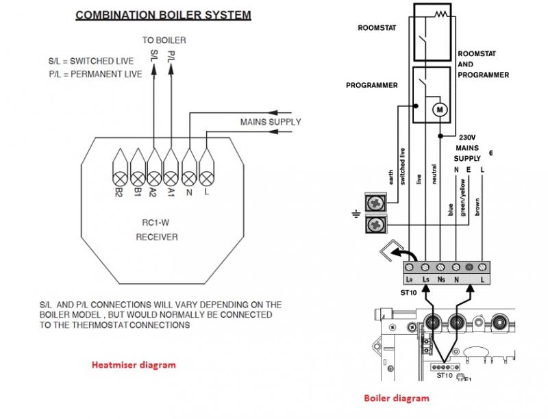
Problem is I don't know how to wire it up. The two diagrams for each product seem to say opposite things? See attached:
Questions:
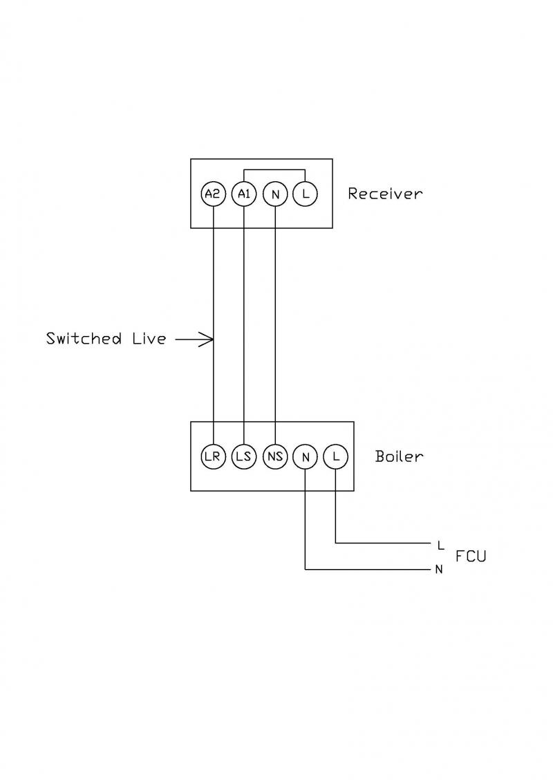
Do I have to remove the cable which currently goes from the FCU to the boiler, and run it from FCU to the receiver instead, and then put a new one on from the receiver to the boiler (as per Heatmiser diagram) or do I just leave the mains supply on the boiler and just connect the receiver to the boiler (as per boiler diagram)?
Which terminals on the boiler do I need to connect to which on the receiver? (eg on heatmiser diagram there are 2 terminals to connect, but on boiler diagram there are 3)
What cable should I connect with 0.75mms 3 core?
Also, what do I do with the existing timer that is attached to the boiler - do I need to remove it and will that break a circuit somewhere?
Many thanks in advance for your help.[/img]
I have a Worcester Bosch Greenstar 25/30si. It currently has a MT10 manual timer on it but the timer dial is broken so I have to switch it on and off. I decided to replace the timer with a Heatmiser wireless programmable thermostat.
Problem is I don't know how to wire it up. The two diagrams for each product seem to say opposite things? See attached:
Questions:
Do I have to remove the cable which currently goes from the FCU to the boiler, and run it from FCU to the receiver instead, and then put a new one on from the receiver to the boiler (as per Heatmiser diagram) or do I just leave the mains supply on the boiler and just connect the receiver to the boiler (as per boiler diagram)?
Which terminals on the boiler do I need to connect to which on the receiver? (eg on heatmiser diagram there are 2 terminals to connect, but on boiler diagram there are 3)
What cable should I connect with 0.75mms 3 core?
Also, what do I do with the existing timer that is attached to the boiler - do I need to remove it and will that break a circuit somewhere?
Many thanks in advance for your help.[/img]