sub circuit confusion

Joined
28 Feb 2022
Messages
70
Reaction score
1
Country
United Kingdom
i am a little confused about mostly testing of sub circuits this is what i get so far and i am basing this off of a shower sub circuit that has a shower cu with a 30ma rcd and a 40a mcb ;; also at the original board there is also a 40a mcb.:

you have to test ze at origin of board, then you basically need to find the r1+r2 and Insulation resistance of the cable that goes from the breaker in the original cu to the top of the rcd terminals in the new board. this is written down as the tests for original board circuit.

once this has been completed you need to start a new collum with the new board. for this you need to test zs or ze at this board which is called zdb but why are you doing this, is this the zs of the cable that goes from origin board to new board?after this you can then test r1+r2, IR, RCD and Zs for the shower circuit in the new board.

is this correct or am i missing key information?

thanks.
 
Sponsored Links
i am a little confused about mostly testing of sub circuits this is what i get so far and i am basing this off of a shower sub circuit that has a shower cu with a 30ma rcd and a 40a mcb ;; also at the original board there is also a 40a mcb.:
You don't really need both MCBs in the shower CU and main CU.

you have to test ze at origin of board,
Ze is measured at the incomer with the Earthing Conductor disconnected - so switch off the Main Switch.
Every other EFLI measurement is Zs at the various locations.

then you basically need to find the R1+R2 and Insulation resistance of the cable that goes from the breaker in the original cu to the top of the rcd terminals in the new board.
Ok Ze + R1 + R2 = Zs at the location. Note upper case R; r is for the end to end of ring circuit conductors.

Insulation esistance is nothing to do with it other than testing the cable is alright.
This and R1+R2 are 'dead tests' and should be done before energising the circuits.

this is written down as the tests for original board circuit.
Not really necessary as the MCB in the shower CU or main CU is superfluous.
Just measure to the shower.

once this has been completed you need to start a new collum with the new board.
If you want to do it that way.

for this you need to test zs or ze at this board which is called zdb
Zdb is just an unofficial way of distinguishing Zs at the main CU.

but why are you doing this,
So that you can add all the R1+R2s to it and determine if satisfactory to operate the Overcurrent Protective Device in the required time.

is this the zs of the cable that goes from origin board to new board?
No, it is the Zs from wherever you are measuring it back to the sub-station.

after this you can then test R1+R2, IR, RCD and Zs for the shower circuit in the new board.
Yes, except you should have done the 'dead tests' already.

is this correct or am i missing key information?
I think you are confusing yourself by having two identical MCBs on one circuit.

Not saying you should but you could wire the shower CU direct from the load side of the Main Switch in the main CU then you can treat each CU separately.
 
Last edited:
so you are saying i could have a small cu with only a 30ma rcd and nothing else? and i’m guessing they put the 40a mcb in with it as if you were tapping into the tails or main switch as you said?

how would you write down the tests on a form as how would you split the cable and put in down as on the certificate as you wouldn’t want to IR and rcd?

i understand why we zs but why at that certain point from rcd terminals back to origin mcb to substation, why not just zs at shower in bathroom as that’s furthest point?

i’m thinking this as maybe i’m confusing it with tapping off the tails and obviously that would need a zdb as it’s a main cu, whereas just an rcd off a mcb wouldn’t as it’s not the origin?

thanks for your response.
 
so you are saying i could have a small cu with only a 30ma rcd and nothing else? and i’m guessing they put the 40a mcb in with it as if you were tapping into the tails or main switch as you said?
Correct.

how would you write down the tests on a form as how would you split the cable and put in down as on the certificate as you wouldn’t want to IR and rcd?
Well, you have Ze at the source.
R1+R2 and IR are measured with the cables disconnected.
If there is more than one cable in the circuit just add them together (or not) depending what you want to record.

i understand why we zs but why at that certain point from rcd terminals back to origin mcb to substation, why not just zs at shower in bathroom as that’s furthest point?
You can record that and it would be fine.

However, you can only determine Ze by a live test and also likely the same for Zdb as you can't disconnect the tails.
Then you add the dead test R1+R2 to Ze to find Zs (at whatever point you want).

i’m thinking this as maybe i’m confusing it with tapping off the tails and obviously that would need a zdb as it’s a main cu, whereas just an rcd off a mcb wouldn’t as it’s not the origin?
Yes.
 
Sponsored Links
i am a little confused about mostly testing of sub circuits this is what i get so far and i am basing this off of a shower sub circuit that has a shower cu with a 30ma rcd and a 40a mcb ;; also at the original board there is also a 40a mcb.:

you have to test ze at origin of board, then you basically need to find the r1+r2 and Insulation resistance of the cable that goes from the breaker in the original cu to the top of the rcd terminals in the new board. this is written down as the tests for original board circuit.

once this has been completed you need to start a new collum with the new board. for this you need to test zs or ze at this board which is called zdb but why are you doing this, is this the zs of the cable that goes from origin board to new board?after this you can then test r1+r2, IR, RCD and Zs for the shower circuit in the new board.

is this correct or am i missing key information?

thanks.
Where is the sub CU relative to the main CU.
Just confirming a 40A MCB in the main CU feeds a sub CU containing 30mA RCD & 40A MCB. What about a main switch?
 
ah i understand. IR testing whole circuit isn’t possible due to rcd and neon indicator, take both legs out of rcd test them individually, do the same with neon indicator and they should be all pass. also rcd doesn’t mess with r1+r2 readings do they?

this makes sense now, i don’t have to take zdb, only zs furthest point at shower, as this is all one circuit, this can also all go in one collum?
 
Where is the sub CU relative to the main CU.
Just confirming a 40A MCB in the main CU feeds a sub CU containing 30mA RCD & 40A MCB. What about a main switch?
this is hypothetical. but i now understand there is no need for the extra mcb as there is already over current protection at main cu.
 
this is hypothetical. but i now understand there is no need for the extra mcb as there is already over current protection at main cu.
Correct there is no need for it. In fact I'd go further and say it's poor practice, especially if the two CU's are not in the same place. My option would have been just a RCD in an enclosure adjacent to the main CU.
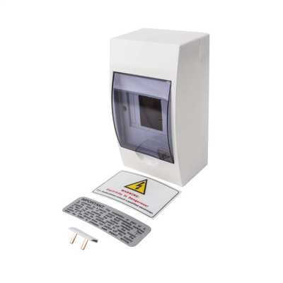
I had a situation a couple of years back where an EICR in advance of a house sale found a 4U enclusure such as
cudis_ecu04_a_a668d18801937059095a107688eb0424.jpg
connected beside the CU with a 25mm conduit coupler and 6mm² singles (actually 7/0.044) direcly off the main switch. It contained 40A MCB for shower, 6A for bathroom light and 30mA RCD covering both. Classified as 'C1' for underrated 6mm² singles.
upload_2022-3-17_23-40-17.png

We added a 40A MCB to the CU and removed 40A MCB from the 4 module enclosure
upload_2022-3-17_23-44-33.png
 
also rcd doesn’t mess with r1+r2 readings do they?
Depends on what you are testing.

The circuits before and after the RCD can be tested.
If you attempt to test R1+R2 for the whole lot through the RCD, it may not provide the results you expect.

Also note that r1 r2 and R1 R2 are totally different things.
R1+R2 is the line conductor and protective conductor resistances for a circuit.
r1 and r2 are the end to end resistances for the line conductor and protective conductor for a ring final circuit.
 
Some RCDs can be tripped by the 200mA DC from a continuity test, therefore not providing any useful results.
 
Some RCDs can be tripped by the 200mA DC from a continuity test, therefore not providing any useful results.
That's probably true, but if the RCD tripped one would be aware of that, and one wouldn't get a result at all (unless, I suppose, one had a meter that could 'hold' a result relating to a very brief period of continuity).

When you said that testing through an RCD "... may not provide the results you expect." I assumed that you meant that it may give an incorrect or misleading result (particularly if nothing 'obvious', like an RCD tripping, 'happened' as a result of one's testing!) - and I can't see how that could happen, can you?

Kind Regards, John
 

DIYnot Local

Staff member

If you need to find a tradesperson to get your job done, please try our local search below, or if you are doing it yourself you can find suppliers local to you.

Select the supplier or trade you require, enter your location to begin your search.


Are you a trade or supplier? You can create your listing free at DIYnot Local

 
Sponsored Links
Back
Top