Texecom Premier Elite 64-W with dual Elite Odyssey 1 external sounders

Joined
26 Oct 2013
Messages
124
Reaction score
1
Location
Essex
Country
United Kingdom
Hi all, would really appreciate if someone could help with some confusion I'm having with the wiring of a Texecom Premier Elite 64-W with dual Elite Odyssey 1 external sounders.

Just to note, this is what I have:

  • Texecom Ricochet Premier Elite 64-W Control Panel
  • 2x Texecom Premier Elite Odyssey 1 External Sounder
  • 6x Texecom Ricochet Impaq SC-W VIBER Accelerometer Technology Wireless Shock and Contact
  • Texecom Premier Elite Satin Chrome SMK Keypad
  • Texecom Connect SmartCom Ethernet & Wifi Communicator
  • 8 Core Burglar Alarm Cable
  • Yuasa Yucel 7-12v Back Up Battery for Alarm Control Panels
  • Texecom Premier Elite Panel USB-COM programming cable


From what I can tell from the installation manual, a "Grade 3" installation requires all 8 cores of the cable:

1658306187625.png


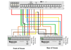
Based on this, I've currently wired both of my sounders as follows:

1658306251986.png


I also read on another document that in order to wire up multiple units, I should remove the white cable that's already in the MSW2 connector, and then connect it to a spare core....

1658306377423.png


This brings up the first question.... I don't appear to have a spare core from what I can tell :)

Does this mean that in order to be able to install this as "Grade 3", I would need to replace the cable with 10-core cable?

Or is it a case that I perhaps don't need to have one of those 8 cables connected to the sounder? For example, the tamper cable (Yellow core on my installation) to complete the circuit between the control panel and both sounders.... should I use that one?


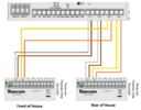
The next part of the confusion is how it's then wired up at the control panel..... this is kind of how I imagine it would be, but of course this doesn't factor in the MSW2 and MSW1 cables?

1658310350105.png


So do I need to upgrade to 10-core?
Have I understood the Fault/Relay (White/Brown) and the Tamper (Yellow) circuits correctly?

Any help with this would be much appreciated :)
 

Attachments

  • 1658309959093.png
    1658309959093.png
    173.4 KB · Views: 88
Sponsored Links
Firstly, this has been covered before and I can see some understanding of the issues involved.

Two 8 cores should be enough, probably more cost effective to stay with 8 core.

As you don't have any physical zones in use I would use the WD monitor for the fault determination and being able to identify which sounder is in fault.

Grading is irrelevant unless you can issue a certificate and NSI or SSAIB registration is needed for this at considerable cost.

8 core cable and using 7 you should have 1 spare core.

best thing to do is wire this on the bench so your sure you have it done correctly.

You don't need both tampers wired from the bell boxes as your joining the tampers together so it would only report the one tamper.
If you wanted both tampers to report separately then you would need to wire them back to the panel.
 
As you don't have any physical zones in use I would use the WD monitor for the fault determination and being able to identify which sounder is in fault.

Thanks, so I should wire the fault relay to two zones on the control panel (even though I only have a single physical zone), and this will allow me to tell which is which from the button panel? Do I program both Z1 and Z2 as "auxiliary"?

1658327345862.png


8 core cable and using 7 you should have 1 spare core.

Which color core (on my diagram) should be the spare core? Yellow?

Do I connect this to the MWS2 cable on the front sounder? Assuming this yellow cable then connects to the yellow cable going to the rear sounder, and then that goes into MSW1?


You don't need both tampers wired from the bell boxes as your joining the tampers together so it would only report the one tamper.
If you wanted both tampers to report separately then you would need to wire them back to the panel.

So if I've understood correctly, I will be able to tell which sounder has a fault from Z1 and Z2, but I won't be able to tell which sounder has been tampered with, I'll just know it's one of them?

Is that correct?


thanks!
 
not unless you wire the tamper relay from each bell box to a zone.

so you could drop the tamper from each bellbox.

ABDS = 4 wires
Fault relay = 2 wires
Tamper relay = 2 Wires total 8 cores

this also saves the misunderstanding of the wires.

Not sure what you mean by this:-
even though I only have a single physical zone
The built in wireless panels have 4 zones inside the panel, I don't see anything on your list other then the bells that would be wired into a zone.


This way you would know which bell box is affected relatively easily.
The programming is in the manual for the bell box and also the panel manual I believe.
 
Sponsored Links
not unless you wire the tamper relay from each bell box to a zone.

so you could drop the tamper from each bellbox.

ABDS = 4 wires

Ok so:

A = 12v = Red
B = Bell = Blue
D = 0V = Black
S = Strobe = Green

Fault relay = 2 wires

Brown, White

Tamper relay = 2 Wires

Orange, Yellow

total 8 cores

this also saves the misunderstanding of the wires.

Not sure what you mean by this:-
The built in wireless panels have 4 zones inside the panel, I don't see anything on your list other then the bells that would be wired into a zone.

Nope nothing else planned for this setup, so basically use all four zones then to be able to determine either a fault or a tamper on each sounder?

So basically, if I wired it like this, I'd know the following:

z1 error = fault on front sounder
z2 error = tamper on front sounder
z3 error = fault on rear sounder
z4 error = tamper on rear sounder

Have I understood that right?

1658335575557.png


This way you would know which bell box is affected relatively easily.
The programming is in the manual for the bell box and also the panel manual I believe.
 

Attachments

  • 1658335165814.png
    1658335165814.png
    130.8 KB · Views: 67
Yes that seems fine the tamper circuit can use tamper as the zone type.

As you are already aware you have to take the power for each bell from a different place on the panel.

any problems post on here with pictures, I would be tempted to run two cables to each bell as you have no spares to play with and it may
 
thanks for all your help!

So based on the 8 cores I do have wired to each bell currently, I could do this?

1658411745103.png


I guess that really only leaves the "Test T" connection on each sounder (assuming I don't need to do anything with the "MSW" wires now?)

In all honestly, its probably easier for me to remove the 8-core wire and replace with new 12-core, than it would be for me to run another extra 8-core wire next to the existing ones, due to the cable path and where cables have been clipped to joists up in the loft.

Is it definitely worth doing, to get that "Test T" connection wire connected to OP1 and OP2 on the control panel?

UPDATE: from what I can see, it offers remote diagnostics from "Test Active" on that connection, so worth doing

If so, I'll order some 12-core and be done with it.

thanks again!
 
Last edited:
Still a bit confused about the MSW thing on the sounders though.... so I don't need to wire MSW2 on the front sounder to MSW1 on the rear sounder at all?
 
if you have 8 core just run two cables but choice is yours. you wouldn't need to join the bells together they would effectively be separate
 
Thanks, genuinely really appreciate it!

Ok I think I'm good to go then I'll swap out the 8-core with 12 core and set it up as follows:

1658431099985.png


Do I need to join Aux connector to Fault connector on the 64-w control panel if it's not being used?

1658446865114.png


Same question for Tamper (C) on both the bell sounders - do they need to be connected to 0v if not being used?

1658447009052.png


Regarding changing the cable, I know it's a waste of perfectly good 8-core, but the two reasons for me swapping out are that 1) I can carefully pop the cable out from the cable clips around the joists in the loft, and then run the new cable under the same clips, rather than needing a hammer to put loads more clips in alongside the old ones, and 2) it means that all the cores will be a different color, so think it makes it a tiny bit easier for me to work with at the control panel in the loft when wiring it in.

thanks again, genuinely appreciate your time replying.
 
Last edited:
Also, just been looking through the manual,

from what I can understand, in my particular setup, I'd set the zones as follows:

z1 (Fault Relay - Front of House Sounder)
Zone Type = 12 Auxiliary
Wiring Type 8 - WD Monitor

z2 (Tamper Relay - Front of House Sounder)
Zone Type = 13 Tamper

z3 (Fault Relay - Rear of House Sounder)
Zone Type = 12 Auxiliary
Wiring Type 8 - WD Monitor

z4 (Tamper Relay - Rear of House Sounder)
Zone Type = 13 Tamper

Presumably, these all go in Area A?
 
The bell tamper to zero volts would have to be linked out at the panel side not required bell side.

rest seems okay any issue post back
 
wired everything up over the weekend, but am getting some errors:

System Alerts:
Panel Lid Tamper (yep, the lid is off the 64-w :) )
Confirm Devices (possibly the Texecom Connect SmartCom?)
EXP 1,1 Tamper (I'm guessing because the 64-w jumper on the right between the two aerials is in commissioning mode?)
Zone 1 Tamper
Zone 2 Tamper
Zone 3 Tamper
Zone 4 Tamper


I'm guessing the zones 1-4 aren't setup right in Wintex

This is how I set them up:

z1 (Fault Relay - Front of House Sounder)
Zone Type = 12 Auxiliary
Wiring Type 8 - WD Monitor

z2 (Tamper Relay - Front of House Sounder)
Zone Type = 13 Tamper
Wiring Type = Normally Closed

z3 (Fault Relay - Rear of House Sounder)
Zone Type = 12 Auxiliary
Wiring Type 8 - WD Monitor

z4 (Tamper Relay - Rear of House Sounder)
Zone Type = 13 Tamper
Wiring Type = Normally Closed

Am I missing a setting somewhere?

thanks
 

DIYnot Local

Staff member

If you need to find a tradesperson to get your job done, please try our local search below, or if you are doing it yourself you can find suppliers local to you.

Select the supplier or trade you require, enter your location to begin your search.


Are you a trade or supplier? You can create your listing free at DIYnot Local

 
Sponsored Links
Back
Top