time delay light switch - confusing wiring

Joined
23 Jan 2022
Messages
4
Reaction score
1
Country
United Kingdom
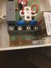
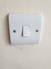
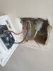
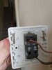
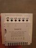
our hallway has 3 lights connected to 5 switches, where one was a time delay switch. All lights switches are connected by 2 wires. when the time delay switch started to fail, we try to replace it. we took off the time delay switch it had 4 connections (see diagram) Live In, Neutral In, Live out and "TRIG". was not able to find any info on the trig connection. New light switch had 3 connections (minus a trig connection). I did not connect the precious trig wire - the new light switches the lights on and off, but none of the other 4 switches work for either on or off - effectively only one switch works now. Not sure of purpose of trig connection or if possible to use existing wiring for a new switch.
 

Attachments

  • 20220123_205707.jpg
    20220123_205707.jpg
    174.2 KB · Views: 102
Sponsored Links
The Trigger connection tends to be used in a Master and Slave system, sometimes its not used, if it was used it would connect to the Trigger connections in the other switches, with a two wire connection i would quess all 5 switches may be wired in parralel
 
Last edited:
thanks for reply. I will take pictures in the morning when I have sunlight.

Effectively was trying to replace the time delay switch with a smart switch.

New light switch has a live in, and a neutral in .. and a live out.

the timer delay switch had 6 wires in total.
2 blue wires in neutral section
2 brown wires in live in section
1 brown wire in Live out
1 brown wire in Trig connection.

I connected all except the trig wire .. and light switches on, only with the smart switch. all of the regular switches do not operate the light on or off. so I am guessing the trig wire is important.

I ordered another timer delay switch from amazon that has a trig connection, but would have preferred to switch to the smart switch.
 
  • Thanks
Reactions: CBW
Sponsored Links
I did see this diagram, and this would suggest i connect the trig wire to Live Out also. I did not connect trig wire to anything, and the other 4 switches have been rendered useless, so I am guessing the wire is needed.
 
NO, do not connect Trigger to Live out, the diagram shows to use just 2 wires to operate the other switches, likely a momentary switch, connected between LIVE IN and the TRIGGER, the other 4 switches will just give a short Live burst to the the Master starting the Time sequence, hence having nothing to the Trigger terminal in the master will render the other 4 switches useless, from your post its unclear what the other 4 switches you have, there may be a way round to connect them without needing a Trigger, i am sure some smart switches can be set up to do it, sort some pics out also of the other switches to indicate how they are connected.
 
ok so I hope these pics make sense

1 pic shows wiring at the old timer delay switch. and another pic shows the back of the smart switch..

Other pics are of the other 4 switches.

we did buy another regular timer delay switch that had a trigger connection, and same thing seems to be happening. not sure if wires got mixed up.
 

Attachments

  • 20220124_121156.jpg
    20220124_121156.jpg
    121.4 KB · Views: 81
  • 20220124_121322.jpg
    20220124_121322.jpg
    228.5 KB · Views: 98
  • 20220124_121332.jpg
    20220124_121332.jpg
    140.3 KB · Views: 168
  • 20220124_180737.jpg
    20220124_180737.jpg
    208.4 KB · Views: 109
  • 20220124_121322.jpg
    20220124_121322.jpg
    228.5 KB · Views: 93
  • other  switch.jpg
    other switch.jpg
    140.3 KB · Views: 81
  • smart switch.jpg
    smart switch.jpg
    96.5 KB · Views: 77
  • wiring .jpg
    wiring .jpg
    208.4 KB · Views: 95
I'd have expected the the 4 normal switches to be daisy chained together, so that 3 (not the last in the chain) would have 2 wires in the COM terminal and 2 wires in the MAKE terminal, is the picture "other switch.jpg" of the switch which is furthest from the Timer switch?
Obviously I'd be very careful, e.g. having the circuit powered off when (un)screwing terminals, but I'd be tempted to park the Trigger wire in a choc block and add a short wire into the Live In terminal. Then, with the power on, briefly poke that short wire into the Trig terminal and see if the lights come on. If they do then it's likely the Trigger circuit is faulty, most likely between the Timer switch and the closest Normal switch.

Edit: On further thought, I'd suggest you follow the Trigger wire until it disappears into the sheath, then is another wire (in that sheath) one of the 2 Live In wires?
 
Last edited:

DIYnot Local

Staff member

If you need to find a tradesperson to get your job done, please try our local search below, or if you are doing it yourself you can find suppliers local to you.

Select the supplier or trade you require, enter your location to begin your search.


Are you a trade or supplier? You can create your listing free at DIYnot Local

 
Sponsored Links
Back
Top