Voltage & switch state identification project

Joined
10 Dec 2008
Messages
835
Reaction score
17
Location
Jersey Marine
Country
United Kingdom
Project
I would like to identify the state of 3 switches, sw 1, 2 & 3 and when power is supplied to a fan …… so 4 indicators – assume these would be LED. I.1 – I.4
Sketch is attached.
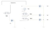
schematic.jpg

The controller is self-contained controller providing Bluetooth, Wireless, time & temperature functions, thermocouple inputs etc .. they all work, providing the 2 ‘conditional’ inputs are satisfied. Then providing variable voltage supply to the fan.

Input 1 – is satisfied when switch one is closed, this is a simple 12V DC cct

Input 2 - is satisfied when Switch 2 & 3 are closed
The output voltage is then provided to the fan, this is a variable voltage from 0 to 12V DC

What I want to ‘add’ are 4 indicators, showing state of each switch, and when there is any power to the fan.
So I would need a way of identifying any voltage present and changing to an on or off ‘switch indication’

Trying to think of an easy way …. I could use a voltage comparator to detect a difference between fan driver voltage & ground, but as there are 2 switches as well …. Assume then its 3 comparators, so getting complicated.
The ‘comparator modules’ are an option https://tinyurl.com/54e89cp6
Hopefully, someone can come up with something simpler than 3 of these.
The switches are spst plungers, with no option to change them to give another set of contacts.


Does anybody have any suggestions, the simpler the better - I have no Arduino skills … just need a few thoughts to start me off
 
Sponsored Links
Not much to go on there.
What's the controller?
You don't show any inputs/outputs, or power.
What are the dash + dot things?
Does the fan really have two switches in series connected to it?
What are the voltage levels?
 
Last edited:
It’s on the sketch …. The controller is not important, it provides a power voltage as explained … 0 to 12V to the fan
This feed is a simple 2wire output, with the 2 switches in series.

i would like to be able to know when there is any power feed to fan
plus the state of the 2 switches
 
The absolutely simplest way - separate the switches from the controller circuit.
Have the switches operate a dpst relay - one side of the output for the indicator, one side for the controller.
 
Sponsored Links
The absolutely simplest way - separate the switches from the controller circuit.
Have the switches operate a dpst relay - one side of the output for the indicator, one side for the controller.
Agree and I could use a fixed 12V for the relays, that would resolve switch issue, still have to detect that there is voltage to fan …. And that can be anything from 0 to 12V
I thought of a voltage parameter … but happy if a simpler way.
 
Last edited:
still have to detect that there is voltage to fan …. And that can be anything from 0 to 10V
Again, simple but crude - just an LED and resistor in parallel - although it would dim at lower voltages.
 
Taken suggestions onboard
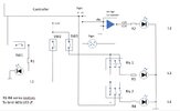
Now it looks like this sketch

I know I need to use current limiting resistors for diodes ... not sure if I need any diode protection for relays, normally add an IN4148 across the coil.
Existing physical switches are unchanged just now driving relays as per suggestion from 'RandomGrinch'

Seems a cheap approach (wish Maplin were still around for bits)


Schematic 2.jpg
 
Neither sketch shows something anyone could make a useful thing from.
To be fair, there was enough information to get the gist of what they wanted.
It might not be the way we would do things, but the OP seems to want things in a specific way, why can't it be useful?

Both the switches need to be closed for the fan to get any power
Yes, both switches need to be on for the fan to get power, but the OP specifically wanted to know the state of each switch
What I want to ‘add’ are 4 indicators, showing state of each switch, and when there is any power to the fan.
And they wanted an easy way of determining the state.
Trying to think of an easy way
There's really not a much easier way than using a couple of relays, especially when you are trying to detect the state of a switch that may otherwise have no power going to it?

You do need resistors. As you have it, LEDs will pop as soon as you close SW2 or 3.
Yes, they need resistors, but we're not talking accurate schematics here. ;)
In #11, the OP states "I know I need to use current limiting resistors for the diodes"

You Still don't show any way to modulate the voltage to the fan. Your switches aren't doing it.
Are there any resistors in the feed to the fan you haven't told us about?
WHat are the voltage levels on the fan? I assume something is working and you have a multimeter? I ask because it matters if they are 11,11.5 and 12V rather than say 3,6,12.
Why do they need to? The OP has stated...
The controller is self-contained controller providing Bluetooth, Wireless, time & temperature functions, thermocouple inputs etc .. they all work, providing the 2 ‘conditional’ inputs are satisfied. Then providing variable voltage supply to the fan.

If you have a voltage which goes from 0 to 12V and want to light LEDs in steps, you can use a LM3914 bargraph driver and a bargraph module and a few passives (cost is less than the postage) if you can use a soldering iron.
You may be reading too much into this, the OP has only asked for an 'Indication' that there is power to the fan...
What I want to ‘add’ are 4 indicators, showing state of each switch, and when there is any power to the fan.
Hence why even a comparator may be overkill!
 
Last edited:
(Abusive post removed)

Others have understood the ask ... apologies if you are not understanding or possibly reading too much into it.
The fan is fully controlled by the controller, the output of which is 0 to 12V, and as its variable speed it can be any voltage up to 12V ... I have measured and at full speed it is 12V.
KEY - I do not wish to change the control system, only to monitor with a single 'on' LED

The controller requires the 3 switches to close for fan to operate, as per sketch 2 of them are in series.
No resistors used.

The controller works, all I want to do is to display the state of the switches and detect when there is 'any' voltage being provided to the fan circuit .. which can be 0-12V
The sketch I provided has all that information.

I do accept that the LED will need series resistance to limit current which for LEDs, for simplicity I had not added them to the sketch, I will probably use 910 Ohm, though I may increase this to limit max current (25mA for LED's I have)

I think I will use 741 Opamp as a Voltage detect circuit .... simply to provide a signal when there is any voltage.
https://www.eleccircuit.com/simple-level-voltage-detector-using-lm741/ simpler and a lot cheaper than LM393 comparator.
If there is an even easier way happy to change.

The suggestions by 'RandomGrinch' about moving switches to relays does allow me to utilize 2nd set of relay contacts to provide a switch state, which meets the ask.

Updated sketch :
Schematic 3.jpg
 
Last edited by a moderator:
(Abusive post removed)
If you don't like my post please feel free to scroll on by, there is no need to be discourteous or insulting this is an open forum.

I am not clueless, the sketch is done using what I have to hand, (PowerPoint), I don't have access to an electrical drawing package to produce using IEC 60617 standard symbols.

I have tried to explain the ask, I'll try again.

What the controller does is not part of this post ........ it works fine, therefore for the purpose of the post there is no need to go into detail of it, nor its various inputs & parameters, displays., software etc.

The key thing is that it drives a DC fan as its output, this output voltage can be anywhere between 0ff (0v) and full speed (+12V)
That all works, and I do not wish to change that.

This is a commercially produced (& wired system) ... the fan output is routed through 2 switches, they are in series, if either is open the fan will not run.

I just wish to 'display' the state of switches via simple LED's and also ideally an LED display that illuminates when there is a request for the fan to operate (when output is any positive voltage)

I did not state relays are needed, they were put forward in this post as a suggested simple solution, and it seems it will fulfill the need of being able to display via an LED and retain the serial switch arrangement with the fan.

... there are no DP switches, only the SPST switches (SW1 -3) as in description. I did show DPST relays after suggestion in the thread, so if they don't use a standard symbol, I'm apologize for that.

... as explained above I don't wish to modulate the fan, the variable voltage to drive the fan is all taken care of by controller, so I am not touching that.

There is no intent to alter the way the system controller provides the variable voltage to the fan.
 
Last edited by a moderator:

DIYnot Local

Staff member

If you need to find a tradesperson to get your job done, please try our local search below, or if you are doing it yourself you can find suppliers local to you.

Select the supplier or trade you require, enter your location to begin your search.


Are you a trade or supplier? You can create your listing free at DIYnot Local

 
Sponsored Links
Back
Top